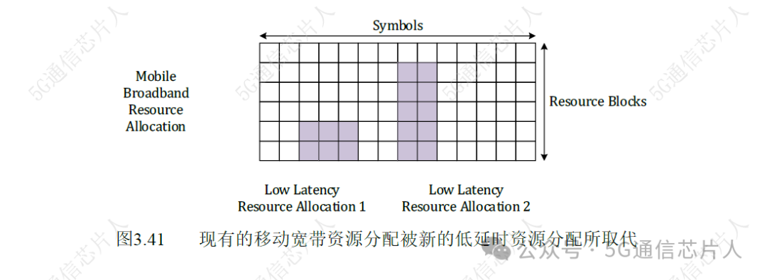
If the resource blocks (RB) within a certain bandwidth part (BWP) are highly utilized, then high-priority services with low latency requirements may need to preempt resource blocks that have already been allocated to another connection.This type of preemption is illustrated in Figure 3.41.
In the example, the packet scheduler allocates a set of resource blocks (RB) for mobile broadband connections. During the transmission of mobile broadband data, the base station (BS) receives some high-priority downlink data for low-latency applications. The packet scheduler identifies the low-latency requirement and immediately schedules resources without waiting for the existing resource allocation to complete.Figure 3.41 shows two examples of resource allocation for low-latency data. The first resource allocation does not affect the existing mobile broadband allocation, while the second resource allocation preempts part of the mobile broadband resources.
Preemption may lead to bit errors and may also corrupt the contents of the HARQ soft combining buffer. Typically, when a user equipment (UE) detects bit errors, it caches the received data and sends a negative acknowledgment to trigger a retransmission. The retransmission is then combined with the original transmission in the soft combining buffer before attempting a second decoding. When preemption occurs, the soft combining buffer contains some samples that do not belong to the expected transmission. This means that the soft combining no longer combines two versions of the same signal.
3GPP has introduced two solutions to help mitigate the impact of preemption. The first solution is based on the “refresh indicator” in the downlink control information (DCI) format 1_1. The second solution is based on a set of “preemption indicators” in the downlink control information (DCI) format 2_1.
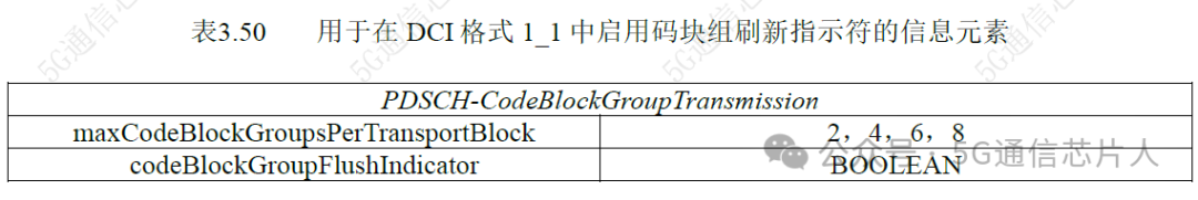
The downlink control information (DCI) format 1_1 can include a code block group (CBG) refresh information (CBGFI) field. For user equipment (UE), support for this field is optional, so the capability information of the user UE must be checked. The user UE indicates whether it supports the CBGFI field through the Phy-ParametersCommon common structure’s cbg-FlushIndication-DL information element. Additionally, the base station (BS) must enable the use of the CBGFI field through the radio resource control (RRC) signaling. This is accomplished through the PDSCH-CodeBlockGroupTransmission parameter structure’s codeBlockGroupFlushIndicator information element. This parameter structure and information element are shown in Table 3.50.
If the CBGFI field is included in the downlink control information (DCI) format 1_1 when allocating resources for retransmission, then a value of ‘0’ indicates that the previously received code block group (CBG) version being retransmitted may be corrupted, and the soft combining buffer should be cleared before filling it with new received data. Conversely, a value of ‘1’ indicates that the previously received code block group (CBG) version can be combined with the newly received data.
The downlink control information (DCI) format 2_1 is used to convey up to 9 groups of preemption indication information. A single group uses 14 bits to represent 14 preemption indication information, meaning the maximum packet size for downlink control information (DCI) format 2_1 is 9 groups × 14 bits = 126 bits. The downlink control information (DCI) format 2_1 is sent to one or more user equipment (UE) using the “interrupt” RNTI (int-RNTI). The interrupt radio network temporary identifier (int-RNTI) is used to encrypt the cyclic redundancy check (CRC) bits of the downlink control information (DCI) format 2_1. All user equipment (UE) extracting a set of preemption indication information from a specific downlink control information (DCI) format 2_1 transmission share the same interrupt radio network temporary identifier (int-RNTI). Similar to downlink control information (DCI) formats 2_0, 2_2, and 2_3, the downlink control information (DCI) format 2_1 is classified as providing a “user group” common signal, as a group of user equipment (UE) can extract content from a single transmission.
The base station (BS) configures the user equipment (UE) to use the downlink control information (DCI) format 2_1 through radio resource control (RRC) signaling. Table 3.51 shows the downlink preemption parameter structure used for this purpose. This parameter structure is used to allocate an interrupt radio network temporary identifier (int-RNTI). It also specifies the total downlink control information (DCI) payload size and where in the payload the user equipment (UE) can find its 14 preemption indications.
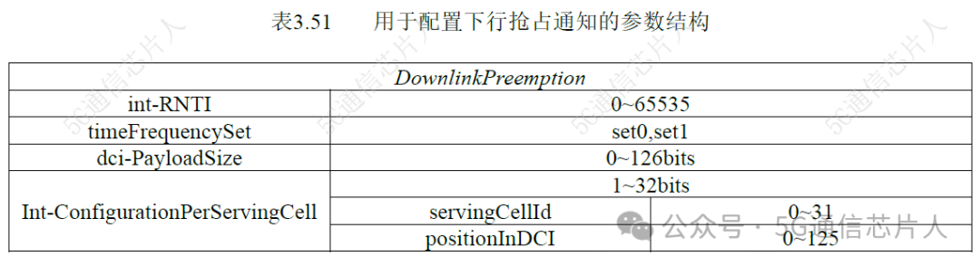
timeFrequencySet information element indicates how to interpret these 14 preemption indications.
If the value of timeFrequencySet is “set 0”, then the PDCCH monitoring period will be divided into 14 time domain intervals. The PDCCH monitoring period corresponds to the periodicity of the search space for DCI format 2_1. This is configured through the monitoring slot periodicity and offset information elements in the search space parameter structure. When configuring DCI format 2_1, this period can be set to 1, 2, or 4 slots. This means that in the case of using a normal cyclic prefix (NCP), each of these 14 time domain intervals can have a duration of 1, 2, or 4 symbols.
Each preemption indication corresponds to a time interval before the received DCI format 2_1 within the search space (SS). The preemption indication is: if any resource block (RB) within the activated downlink bandwidth part (BWP) is preempted during that time interval, it is set to “1”. The upper part of Figure 3.42 shows examples of preemption indications for a search space (SS) period of 1 and 2 slots, for a time frequency set of “set 0”. These examples are based on the preemption scenarios shown in Figure 3.41. For a period of 2 slots, it is assumed that preemption occurs in the second slot.
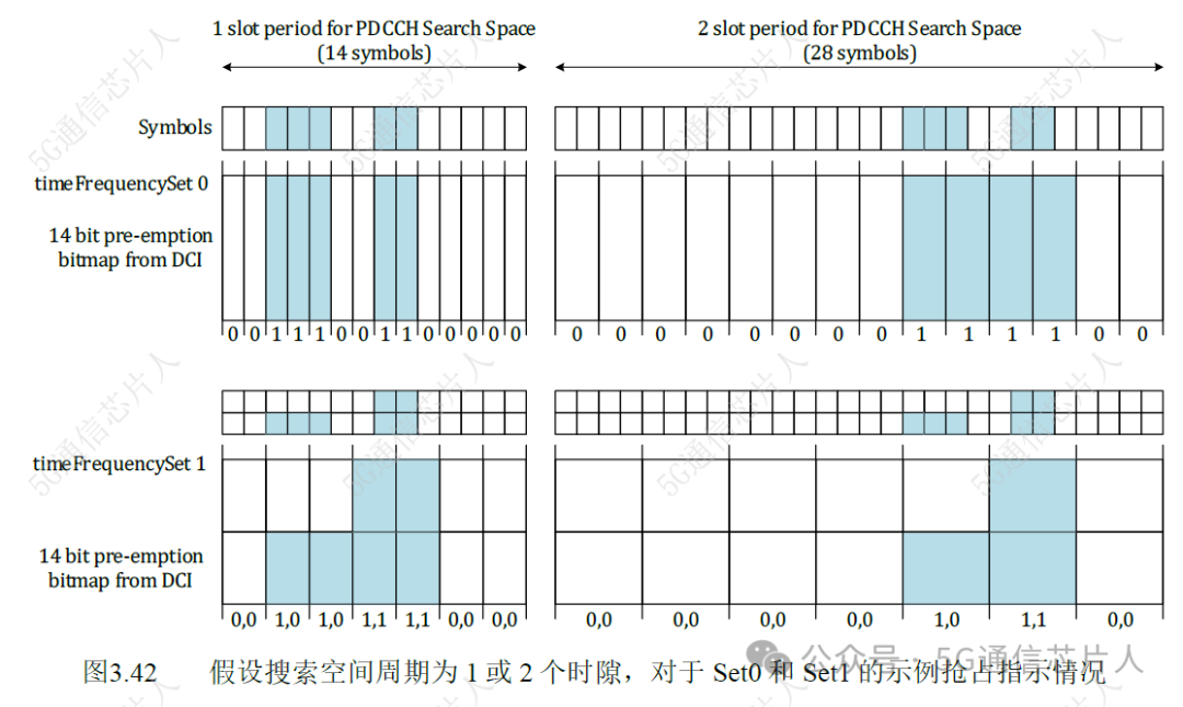
If the value of timeFrequencySet is “set 1”, then the PDCCH monitoring period will be divided into 7 time domain intervals and 2 frequency domain intervals. Each frequency domain interval corresponds to half of the activated downlink (DL) bandwidth part (BWP).
Each preemption indication corresponds to all previous time/frequency intervals within the search space where DCI format 2_1 has been received. If any resource block (RB) within the activated downlink (DL) bandwidth part (BWP) is preempted during that time/frequency interval, the preemption indication is set to “1”. The lower part of Figure 3.42 shows examples of preemption indications for a time/frequency set of “set 1” when the search space period is 1 and 2 slots. These examples are also derived from the preemption scenarios shown in Figure 3.41.
These preemption indications have limited resolution, so overall, they show a higher degree of preemption than what actually occurs. The first preemption in Figure 3.41 does not affect the mobile broadband resource allocation, so the base station (BS) can decide to exclude this preemption from the preemption indication set. This avoids unnecessary data loss for the user equipment (UE). If the preemption indication is used by multiple user equipment (UE), it may be necessary to include this preemption, as it may have affected at least one user equipment (UE). If the relevant downlink data has been successfully decoded, then these preemption indications will not affect the user equipment (UE).