1. Introduction
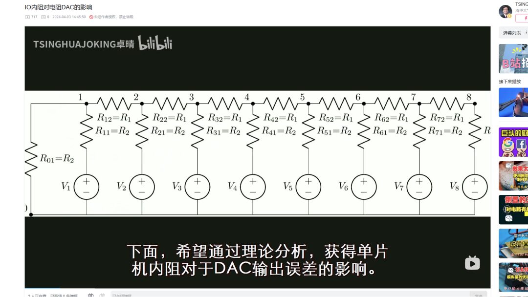
Today, I derived the output formula for an 8-bit resistor DAC, calculating the impact of the microcontroller’s IO port resistance on the DAC’s linear accuracy. Now that I have some time left, I will patiently derive the analytical formula for the output voltage of a 15-bit DAC to verify whether the microcontroller’s IO resistance affects the DAC in relation to the number of channels.
2. Derivation Process
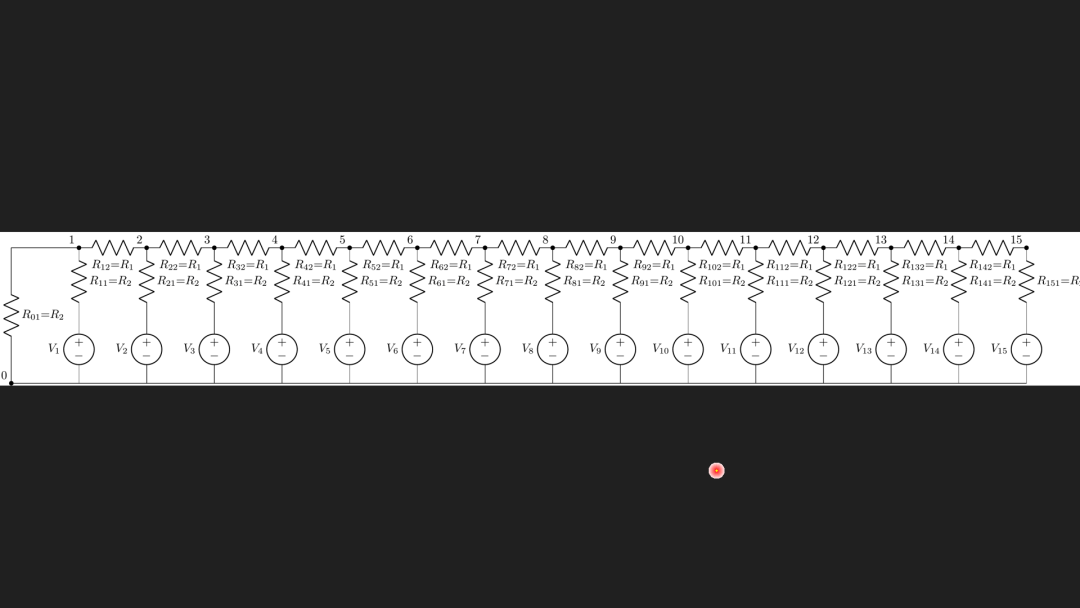
The theoretical formula for the DAC was still generated using the LCA software package from this morning, only this time the circuit structure was increased to 15 channels. This is the circuit diagram of the R2R resistor DAC drawn by LCA. After that, it generated the analytical expression for the output of the final circuit. This solving process took about 10 minutes on the computer.
#!/usr/local/bin/python
# -*- coding: gbk -*-
#******************************
# TEST1.PY                   - by Dr. ZhuoQing 2024-04-03
#
# Note:
#******************************

from headm import *
from sympy                  import symbols,simplify,expand,print_latex
from sympy                  import *
from lcapy                  import *
from sympy                  import symbols,simplify,expand,print_latex
from sympy                  import *

#------------------------------------------------------------
cct = Circuit("""

V1   1_0 0_1 dc V1  ; down
W0   0  0_1         ; right
R01  0  0_0   R2    ; up
R11  1_0 1    R2    ; up
W00  1  0_0         ; left

R12  1 2      R1    ; right
W1   0_1 0_2        ; right
V2   2_0 0_2 dc V2  ; down
R21  2_0 2    R2    ; up

R22  2 3      R1    ; right
W2   0_2 0_3        ; right
V3   3_0 0_3 dc V3  ; down
R31  3_0 3    R2    ; up

R32  3 4      R1    ; right
W3   0_3 0_4        ; right
V4   4_0 0_4 dc V4  ; down
R41  4_0 4    R2    ; up

R42  4 5      R1    ; right
W4   0_4 0_5        ; right
V5   5_0 0_5 dc V5  ; down
R51  5_0 5    R2    ; up

R52  5 6      R1    ; right
W5   0_5 0_6        ; right
V6   6_0 0_6 dc V6  ; down
R61  6_0 6    R2    ; up

R62  6 7      R1    ; right
W6   0_6 0_7        ; right
V7   7_0 0_7 dc V7  ; down
R71  7_0 7    R2    ; up

R72  7 8      R1    ; right
W7   0_7 0_8        ; right
V8   8_0 0_8 dc V8  ; down
R81  8_0 8    R2    ; up

R82  8 9      R1    ; right
W8   0_8 0_9        ; right
V9   9_0 0_9 dc V9  ; down
R91  9_0 9    R2    ; up

R92  9 10     R1    ; right
W9   0_9 0_10        ; right
V10  10_0 0_10 dc V10 ; down
R101 10_0 10    R2    ; up

R102 10 11     R1    ; right
W10  0_10 0_11      ; right
V11  11_0 0_11 dc V11 ; down
R111 11_0 11    R2    ; up

R112 11 12     R1    ; right
W11  0_11 0_12      ; right
V12  12_0 0_12 dc V12 ; down
R121 12_0 12    R2    ; up

R122 12 13     R1    ; right
W12  0_12 0_13      ; right
V13  13_0 0_13 dc V13 ; down
R131 13_0 13    R2    ; up

R132 13 14     R1    ; right
W13  0_13 0_14      ; right
V14  14_0 0_14 dc V14 ; down
R141 14_0 14    R2    ; up

R142 14 15     R1    ; right
W14  0_14 0_15      ; right
V15  15_0 0_15 dc V15 ; down
R151 15_0 15    R2    ; up

""")

#------------------------------------------------------------
import pyautogui

schfn = r'd:\temp\cct.png'
cct.draw(schfn)

rect = tspgetwindowrect(schfn.split('\\')[-1])
pyautogui.FAILSAFE = False
if sum(rect) != 0:
    pyautogui.click(rect[2]-30, rect[1]+15)
os.startfile(schfn)
printf('\a')
tspfocuswindow("TEASOFT:3")

#------------------------------------------------------------
result = cct[15].V(t)
printf(result)
exit()

#------------------------------------------------------------
mstr = latex(result)
printf(mstr)
_=tspexecutepythoncmd("msg2latex")

#------------------------------------------------------------
#        END OF FILE : TEST1.PY
#******************************
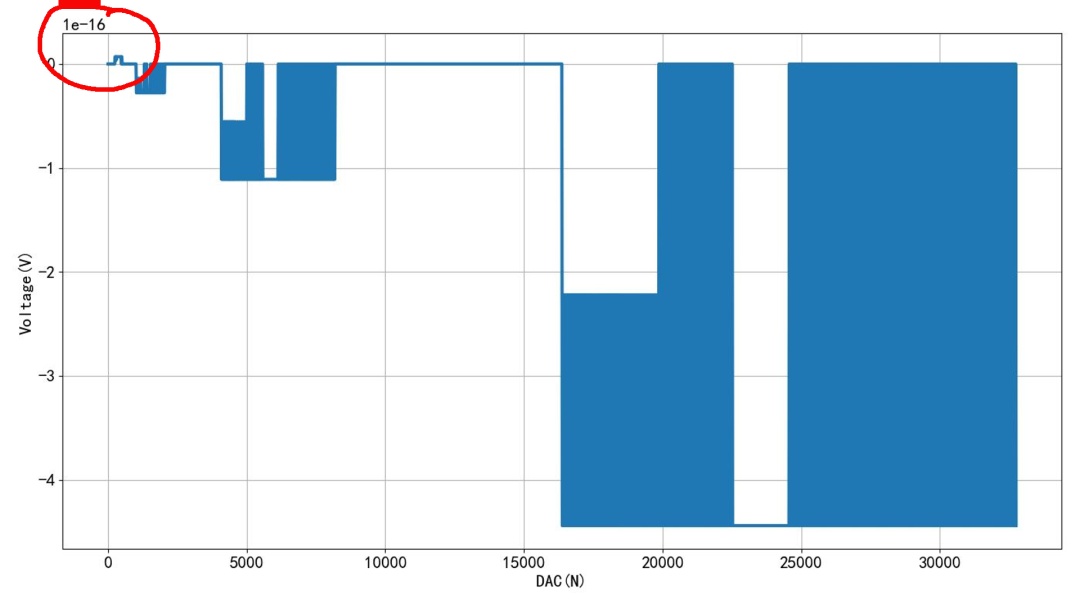
▲ Figure 1.2.1 15-Bit DAC StructureUsing LCA to derive the output voltage formula, I converted it into a Python program. This allows for the calculation of the output of the resistor network under different DAC values. It can be seen that with R1 and R2 being 10k and 20k ohms respectively, the output voltage shows a strict linear relationship with the DAC value. The error between the output voltage and the theoretical DAC value is the same as the theoretical value, aside from minor errors caused by the computer’s floating-point precision.
#!/usr/local/bin/python
# -*- coding: gbk -*-
#******************************
# TEST3.PY                   - by Dr. ZhuoQing 2024-04-03
#
# Note:
#******************************

from headm import *

def Dr1r2(R1,R2):
    return 2*R1**14 + 55*R1**13*R2 + 676*R1**12*R2**2 + 4900*R1**11*R2**3 + 23276*R1**10*R2**4 +\
           76153*R1**9*R2**5 + 175560*R1**8*R2**6 + 286824*R1**7*R2**7 + 329460*R1**6*R2**8 +\
           260338*R1**5*R2**9 + 136136*R1**4*R2**10 + 44200*R1**3*R2**11 + 8008*R1**2*R2**12 + 665*R1*R2**13 + 16*R2**14

def N1(R1,R2):
    return R2**14

def N10(R1,R2):
    return (2*R1**9*R2**5 + 33*R1**8*R2**6 + 225*R1**7*R2**7 + 819*R1**6*R2**8 + 1716*R1**5*R2**9 +
            2079*R1**4*R2**10 + 1386*R1**3*R2**11 + 450*R1**2*R2**12 + 54*R1*R2**13 + R2**14)

def N11(R1,R2):
    return (2*R1**10*R2**4 + 37*R1**9*R2**5 + 289*R1**8*R2**6 + 1240*R1**7*R2**7 + 3185*R1**6*R2**8 +
            5005*R1**5*R2**9 + 4719*R1**4*R2**10 + 2508*R1**3*R2**11 + 660*R1**2*R2**12 + 65*R1*R2**13 + R2**14)

def N12(R1,R2):
    return (2*R1**11*R2**3 + 41*R1**10*R2**4 + 361*R1**9*R2**5 + 1785*R1**8*R2**6 + 5440*R1**7*R2**7 +
            10556*R1**6*R2**8 + 13013*R1**5*R2**9 + 9867*R1**4*R2**10 + 4290*R1**3*R2**11 + 935*R1**2*R2**12 + 77*R1*R2**13 + R2**14)

def N13(R1,R2):
    return (2*R1**12*R2**2 + 45*R1**11*R2**3 + 441*R1**10*R2**4 + 2470*R1**9*R2**5 + 8721*R1**8*R2**6 +
            20196*R1**7*R2**7 + 30940*R1**6*R2**8 + 30888*R1**5*R2**9 + 19305*R1**4*R2**10 + 7007*R1**3*R2**11 +
            1287*R1**2*R2**12 + 90*R1*R2**13 + R2**14)

def N14(R1,R2):
    return (2*R1**13*R2 + 49*R1**12*R2**2 + 529*R1**11*R2**3 + 3311*R1**10*R2**4 + 13300*R1**9*R2**5 +
            35853*R1**8*R2**6 + 65892*R1**7*R2**7 + 82212*R1**6*R2**8 + 68068*R1**5*R2**9 + 35750*R1**4*R2**10 +
            11011*R1**3*R2**11 + 1729*R1**2*R2**12 + 104*R1*R2**13 + R2**14)

def N15(R1,R2):
    return (2*R1**14 + 53*R1**13*R2 + 625*R1**12*R2**2 + 4324*R1**11*R2**3 + 19481*R1**10*R2**4 + 59983*R1**9*R2**5 +
            128877*R1**8*R2**6 + 193800*R1**7*R2**7 + 201552*R1**6*R2**8 + 140998*R1**5*R2**9 + 63206*R1**4*R2**10 +
            16744*R1**3*R2**11 + 2275*R1**2*R2**12 + 119*R1*R2**13 + R2**14)

def N2(R1,R2):
    return (2*R1*R2**13 + R2**14)

def N3(R1,R2):
    return (2*R1**2*R2**12 + 5*R1*R2**13 + R2**14)

def N4(R1,R2):
    return (2*R1**3*R2**11 + 9*R1**2*R2**12 + 9*R1*R2**13 + R2**14)

def N5(R1,R2):
    return (2*R1**4*R2**10 + 13*R1**3*R2**11 + 25*R1**2*R2**12 + 14*R1*R2**13 + R2**14)

def N6(R1,R2):
    return (2*R1**5*R2**9 + 17*R1**4*R2**10 + 49*R1**3*R2**11 + 55*R1**2*R2**12 + 20*R1*R2**13 + R2**14)

def N7(R1,R2):
    return (2*R1**6*R2**8 + 21*R1**5*R2**9 + 81*R1**4*R2**10 + 140*R1**3*R2**11 + 105*R1**2*R2**12 + 27*R1*R2**13 + R2**14)

def N8(R1,R2):
    return (2*R1**7*R2**7 + 25*R1**6*R2**8 + 121*R1**5*R2**9 + 285*R1**4*R2**10 + 336*R1**3*R2**11 +
            182*R1**2*R2**12 + 35*R1*R2**13 + R2**14)

def N9(R1,R2):
    return (2*R1**8*R2**6 + 29*R1**7*R2**7 + 169*R1**6*R2**8 + 506*R1**5*R2**9 + 825*R1**4*R2**10 + 714*R1**3*R2**11 +
            294*R1**2*R2**12 + 44*R1*R2**13 + R2**14)

#------------------------------------------------------------
def DAC15(number, r1, r2):
    D = Dr1r2(r1,r2)
    Ndim = [N15(r1,r2), N14(r1,r2), N13(r1,r2),
            N12(r1,r2), N11(r1,r2),
            N10(r1,r2), N9(r1,r2),
            N8(r1,r2), N7(r1,r2), N6(r1,r2),
            N5(r1,r2), N4(r1,r2), N3(r1,r2),
            N2(r1,r2), N1(r1,r2)]

    nstr = bin(number)[2:]
    nstr = '0'*(15-len(nstr)) + nstr

    number = [int(s)*n/D for s,n in zip(nstr, Ndim)]
    return sum(number)

#------------------------------------------------------------
r1 = 10e3
r2 = 20e3+50
v = DAC15(0x8000, r1, r2)
Vmax = 3.3

ddim = arange(0, 0x7fff, 0x10)
vdim = [DAC15(d,r1,r2)*Vmax for d in ddim]
odim = [d*Vmax/0x8000 for d in ddim]
edim = [v1-v2 for v1,v2 in zip(vdim, odim)]

plt.plot(ddim, edim, lw=3)

plt.xlabel("DAC(N)")
plt.ylabel("Voltage(V)")
plt.grid(True)
plt.tight_layout()
plt.show()

#------------------------------------------------------------
printf("\a")

#------------------------------------------------------------
#        END OF FILE : TEST3.PY
#******************************
This calculates the DAC output error by increasing R2 by 50 ohms to simulate the output resistance of the microcontroller’s IO port. The error is approximately 13mV, which is the same as the error corresponding to the 8-channel case this morning. This indicates that the absolute value of the linear error caused by the microcontroller’s IO port resistance is independent of the number of channels.
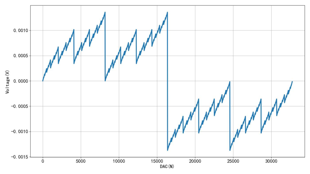
▲ Figure 1.2.2 Linear Error After Increasing R2 by 50 Ohms※ Conclusion ※
This article derived the output voltage expression for a 15-bit resistor DAC. By increasing the R2 resistance by 50 ohms, the output error of the DAC was calculated, verifying that the R2R resistor network is affected by the output resistance of the microcontroller’s IO port. The magnitude of the error is unrelated to the number of channels. The simulation Python program and data can be found in the CSDN article. This lays a foundation for further theoretical analysis of the resistor DAC.