1. Choosing Pull-Up Resistors for Microcontrollers
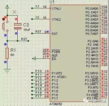
As can be seen in the reset circuit, when resistor R1=10k, RST is high, but when R1=50, RST is low. Clearly, R1=10k is incorrect, as the microcontroller remains in the reset state and cannot function. This occurs because the RST pin contains a transistor, which allows a small cutoff current even when off. When R is very large, the weak cutoff current results in a high level.
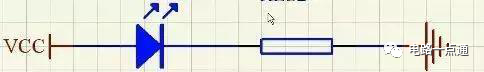
2. Calculating Series Resistors for LEDs
Typically, red surface-mounted LEDs have a voltage of 1.6V-2.4V and a current of 2-20mA. Brightness varies between 2-5mA, with little change in brightness above 5mA.
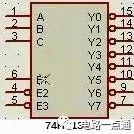
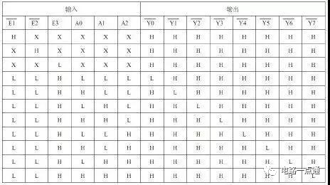
3. Insufficient Ports
In this case, expansion chips can be used, such as the 74HC138 decoder for expansion.
4. Filter Capacitors
Filter capacitors are divided into high-frequency and low-frequency types.
1. High-frequency filter capacitors typically use 104 capacitors (0.1uF) to short-circuit high-frequency components and protect devices from high-frequency interference. These should be added between the power supply and ground of ordinary ICs to eliminate high-frequency interference (like electrostatic discharge).
2. Low-frequency filter capacitors generally use electrolytic capacitors (100uF) to remove low-frequency ripple, store energy, and stabilize the power supply. They are mostly placed at power interfaces, next to high-power components, such as USB ports and stepper motors, with a voltage rating at least twice the maximum system voltage.
5. Functions of Transistors
1. Switch Function:
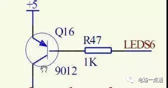
When LEDS6 is high, it is off; when low, it is on.
Calculating the limiting resistor: if the collector current is I, then the base current is I/100 (this involves amplification, where the collector current is 100 times the base current). The PN junction voltage is 0.7V, so R=(5-0.7)/(I/100).
2. Amplification Function:
The collector current is 100 times the base current.
3. Level Conversion:
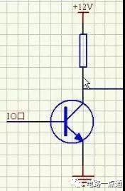
When the base is high, the transistor conducts, grounding the right-side wire to low; when the base is low, the transistor is off, and the output is high.
6. Issues Related to Seven-Segment Displays
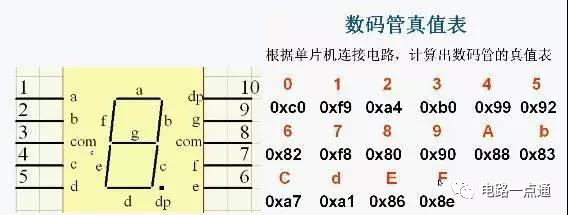
The digits formed by lighting the seven-segment display are composed of a, b, c, d, e, f, g, and dp (decimal point), as shown in the truth table above.
7. Current and Voltage Drive Issues
Due to the limited output of microcontrollers, when there are many loads, additional driver chips, such as the 74HC245, are needed.
8. Pull-Up Resistors
Principles for selecting pull-up resistors:
1. To save power and consider the chip’s current sinking capability, the resistor should be sufficiently large; a large resistor means low current.
2. To ensure sufficient driving current, the resistor should be sufficiently small; a small resistor means high current.
3. For high-speed circuits, excessively large pull-up resistors may cause the edge to become sluggish.
Considering all factors, the common values for pull-up resistors are selected between 1K and 10K, with the same for pull-down resistors.
Pull-up and pull-down resistors:
Pull-up means keeping an uncertain signal at high level through a resistor; pull-down is similar.
1. Level conversion, increasing output level parameters.
2. OC gates must have pull-up resistors to function.
3. Increase the driving capacity of ordinary IO pins.
4. Floating pins need pull-up or pull-down resistors for anti-interference.
9. Crystal Oscillator and Reset Circuits
Crystal oscillator circuit:
1. Crystal selection:
Select based on actual system requirements, such as 6M, 12M, 11.0592M, 20M, etc.
2. Load capacitance:
Connect two capacitors of 10 to 30pF to ground, commonly using 20pF.
3. Measuring the crystal oscillator with a multimeter:
Directly connect the red probe to the crystal pin and the black probe to GND to measure the voltage.
Reset circuit:
Resetting sets the internal circuits of the microcontroller to a defined state, initializing all registers.
The reset time for the 51 microcontroller is approximately 2 mechanical cycles, but specifics should refer to the chip’s datasheet.
Generally, a reset chip or reset circuit is used, with specific resistor-capacitor parameters calculated via Google searches.
10. Key Bounce and Elimination
Keys are also mechanical devices, and pressing or releasing them can cause bouncing, as shown in the image below:
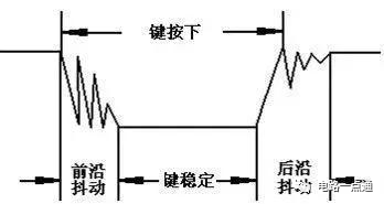
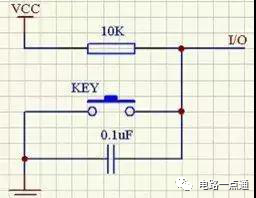
There are two methods to eliminate bouncing: software debounce and hardware debounce, where hardware debounce uses capacitors to short high-frequency signals.
Microcontroller C Language Programming Guide, Essential for Beginners
Classic 51 Microcontroller Introductory Tutorial (Excellent Tutorial)
Comprehensive Examples of Microcontroller Programming
Compilation of Microcontroller Interface Materials (50 volumes)
Complete Version of Learning Microcontrollers in Ten Days
Microcontroller Peripheral Circuit Design
100 Examples of Microcontroller Programming Techniques