Today, I want to take you into the fascinating world of automotive electronic systems, much like lifting the hood to observe the beating heart of a car. Have you ever encountered a situation where, when your beloved car suddenly lights up the malfunction indicator, a mechanic connects a mysterious device to the OBD interface to decode the fault code? This is all thanks to the precise operation of ECU diagnostic data transmission! Let’s imagine a vivid scenario: when the vehicle’s ECU feels unwell, the diagnostic tool acts like a doctor with a stethoscope, gently asking, “How are you feeling now?” The engine ECU responds with 0x50 Extended Session Confirmation, just like a patient opening their medical record to cooperate with the examination. This question-and-answer process is reminiscent of a consultation in a hospital, except here the “treatment manual” is written in mysterious hexadecimal code~ These important data cannot be transmitted through just any channel. Just like my local delivery station has different types of transport vehicles, the vehicle’s system is equipped with six dedicated transport channels. There are high-speed Ethernet “highways” that can reach 1Gbps, as well as LIN “country roads” suitable for a slower pace. Among them, the classic CAN bus is particularly noteworthy; it is like a diligent delivery person, transmitting “health reports” between ECUs at speeds ranging from 125kbps to 1Mbps.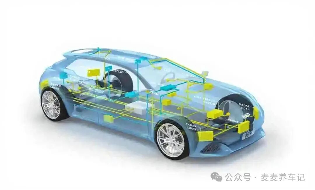 When it comes to specific transmission methods, this is where the wisdom of engineers shines. When the data volume is small, single-frame messages are like sending a postcard, with an 8-byte small package delivered directly. For example, when reading the software version number with the 0x22 F1 90 service, the diagnostic tool sends a 3-byte “note,” and the ECU immediately replies with a 6-byte “memo,” making the entire process smooth and efficient. If a large package of 34 bytes needs to be transmitted, then multi-frame messages must be initiated for relay transmission. The first frame indicates the total number of packages, the flow control frame acts like a dispatcher coordinating the loading rhythm, and the consecutive frames are like queued delivery boxes. I remember once witnessing the ECU transmitting frozen frame data; the first frame reported, “There are 3 boxes of delivery,” and the diagnostic tool immediately replied, “Each vehicle carries 3 boxes, departing every 20 seconds,” making the entire process orderly and exciting to watch! During this process, there is a particularly thoughtful design known as the flow control frame waiting command. Just like a delivery person confirming with the recipient, “Is it okay to deliver tomorrow?” when they find the recipient is not at home, this clever mechanism effectively avoids the awkwardness of data packages being rejected when the receiving buffer is nearly full. Observing these intricate protocol designs, I can’t help but admire the ingenuity of automotive engineers. From the most basic 0/1 signals to complex diagnostic data parsing, every step embodies a culmination of wisdom. Next time your car’s malfunction light comes on, you can imagine the ECUs accurately transmitting the “health check report” through these meticulously designed channels! I know these technical terms can sound a bit overwhelming, but as long as we grasp the core logic of “diagnosis – transmission – parsing,” it becomes as simple as understanding the delivery process. Remember, whether it’s a quick single-frame package or a heavy multi-frame transport, the ultimate goal is to ensure that the vehicle’s “health data” is delivered accurately. If you want to learn more about the detailed diagnostic process, be sure to visit my blog regularly for more insights into the fascinating world of automotive electronics!