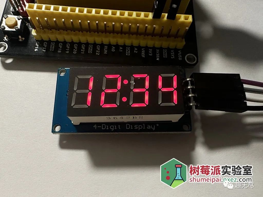
This tutorial focuses on how to use the TM1637 4-digit display module on the Raspberry Pi Pico.
Required Components
– Raspberry Pi Pico or Pico W
– TM1637 4-digit display module
– Breadboard and jumper wires
– microUSB data cable
TM1637 is an LED (Light Emitting Diode) driver control circuit with a keyboard scanning interface, integrating MCU digital interface, data latch, LED high voltage drive, keyboard scanning, and other circuits. The TM1637 driven display module is popular due to its low number of control pins. Out of these 4 pins, two are power pins, and the other two control the displayed values on the module.
Pin Name Function
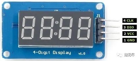
CLK clock pin helps to keep the clock pulses synchronized between the module and the microcontroller. DIO data pin helps to send and receive data from the microcontroller. GND ground (GND) is used to establish a common ground with external devices. VCC power (VCC) input pin is used to power the module. Accepts 3.3-5V VCC.
Raspberry Pi Pico I2C Pins
The RP2040 chip has two I2C controllers. Both I2C controllers can be accessed through the GPIO pins of the Raspberry Pi Pico. The table below shows the connection between GPIO pins and the two I2C controllers. Each controller connection can be configured through multiple GPIO pins as shown in the diagram. However, before using the I2C controller, you should configure the GPIO pins to be used with a specific I2C controller in the software.
I2C Controller GPIO Pins
I2C0 – SDA GP0/GP4/GP8/GP12/GP16/GP20
I2C0 – SCL GP1/GP5/GP9/GP13/GP17/GP21
I2C1 – SDA GP2/GP6/GP10/GP14/GP18/GP26
I2C1 – SCL GP3/GP7/GP11/GP15/GP19/GP27
The connection between the two devices is quite simple. We connect CLK to GP26 and DIO to GP27. You can also use other SDA/SCL pin combinations as shown in the table above.
Please follow the diagram below: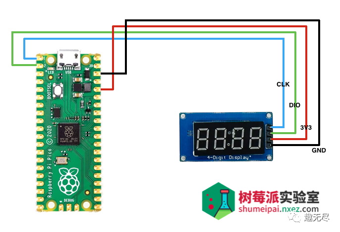
Installing TMP1637 Library
To program the Raspberry Pi Pico using the TM1637 display module, we need the TM1637 library from GitHub.
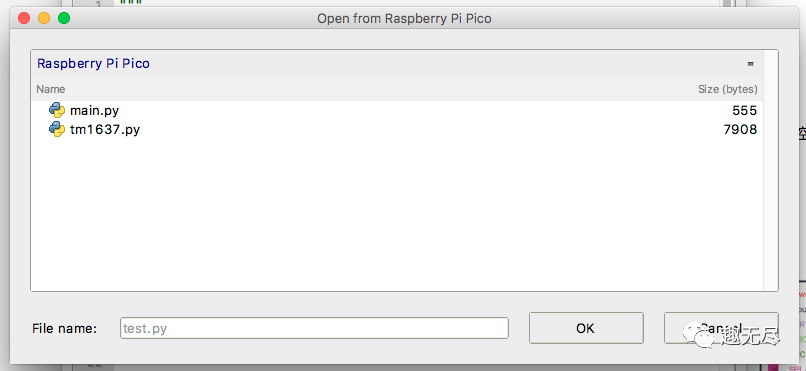
Copy this library and save it as tm1637.py on the Raspberry Pi Pico. Open a new file in Thonny. Copy the library provided below or get it from this link. Save it to the Raspberry Pi Pico as tm1637.py, either in the root directory or the lib folder.
from micropython import const
from machine import Pin
from time import sleep_us, sleep_ms
TM1637_CMD1 = const(64)  # 0x40 data command
TM1637_CMD2 = const(192) # 0xC0 address command
TM1637_CMD3 = const(128) # 0x80 display control command
TM1637_DSP_ON = const(8) # 0x08 display on
TM1637_DELAY = const(10) # 10us delay between clk/dio pulses
TM1637_MSB = const(128)  # msb is the decimal point or the colon depending on your display
# 0-9, a-z, blank, dash, star
SEGMENTS = bytearray(b'\x3F\x06\x5B\x4F\x66\x6D\x7D\x07\x7F\x6F\x77\x7C\x39\x5E\x79\x71\x3D\x76\x06\x1E\x76\x38\x55\x54\x3F\x73\x67\x50\x6D\x78\x3E\x1C\x2A\x76\x6E\x5B\x00\x40\x63')
class TM1637(object):
    """Library for quad 7-segment LED modules based on the TM1637 LED driver."""
    def __init__(self, clk, dio, brightness=7):
        self.clk = clk
        self.dio = dio
        if not 0 <= brightness <= 7:
            raise ValueError("Brightness out of range")
        self._brightness = brightness
        self.clk.init(Pin.OUT, value=0)
        self.dio.init(Pin.OUT, value=0)
        sleep_us(TM1637_DELAY)
        self._write_data_cmd()
        self._write_dsp_ctrl()
    def _start(self):
        self.dio(0)
        sleep_us(TM1637_DELAY)
        self.clk(0)
        sleep_us(TM1637_DELAY)
    def _stop(self):
        self.dio(0)
        sleep_us(TM1637_DELAY)
        self.clk(1)
        sleep_us(TM1637_DELAY)
        self.dio(1)
    def _write_data_cmd(self):
        # automatic address increment, normal mode
        self._start()
        self._write_byte(TM1637_CMD1)
        self._stop()
    def _write_dsp_ctrl(self):
        # display on, set brightness
        self._start()
        self._write_byte(TM1637_CMD3 | TM1637_DSP_ON | self._brightness)
        self._stop()
    def _write_byte(self, b):
        for i in range(8):
            self.dio((b >> i) & 1)
            sleep_us(TM1637_DELAY)
            self.clk(1)
            sleep_us(TM1637_DELAY)
            self.clk(0)
            sleep_us(TM1637_DELAY)
        self.clk(0)
        sleep_us(TM1637_DELAY)
        self.clk(1)
        sleep_us(TM1637_DELAY)
        self.clk(0)
        sleep_us(TM1637_DELAY)
    def brightness(self, val=None):
        """Set the display brightness 0-7."""
        # brightness 0 = 1/16th pulse width
        # brightness 7 = 14/16th pulse width
        if val is None:
            return self._brightness
        if not 0 <= val <= 7:
            raise ValueError("Brightness out of range")
        self._brightness = val
        self._write_data_cmd()
        self._write_dsp_ctrl()
    def write(self, segments, pos=0):
        """Display up to 6 segments moving right from a given position.
        The MSB in the 2nd segment controls the colon between the 2nd
        and 3rd segments."""
        if not 0 <= pos <= 5:
            raise ValueError("Position out of range")
        self._write_data_cmd()
        self._start()
        self._write_byte(TM1637_CMD2 | pos)
        for seg in segments:
            self._write_byte(seg)
        self._stop()
        self._write_dsp_ctrl()
    def encode_digit(self, digit):
        """Convert a character 0-9, a-f to a segment."""
        return SEGMENTS[digit & 0x0f]
    def encode_string(self, string):
        """Convert an up to 4 character length string containing 0-9, a-z,
        space, dash, star to an array of segments, matching the length of the
        source string."""
        segments = bytearray(len(string))
        for i in range(len(string)):
            segments[i] = self.encode_char(string[i])
        return segments
    def encode_char(self, char):
        """Convert a character 0-9, a-z, space, dash or star to a segment."""
        o = ord(char)
        if o == 32:
            return SEGMENTS[36] # space
        if o == 42:
            return SEGMENTS[38] # star/degrees
        if o == 45:
            return SEGMENTS[37] # dash
        if o >= 65 and o <= 90:
            return SEGMENTS[o-55] # uppercase A-Z
        if o >= 97 and o <= 122:
            return SEGMENTS[o-87] # lowercase a-z
        if o >= 48 and o <= 57:
            return SEGMENTS[o-48] # 0-9
        raise ValueError("Character out of range: {:d} '{:s}'".format(o, chr(o)))
    def hex(self, val):
        """Display a hex value 0x0000 through 0xffff, right aligned."""
        string = '{:04x}'.format(val & 0xffff)
        self.write(self.encode_string(string))
    def number(self, num):
        """Display a numeric value -999 through 9999, right aligned."""
        # limit to range -999 to 9999
        num = max(-999, min(num, 9999))
        string = '{0: >4d}'.format(num)
        self.write(self.encode_string(string))
    def numbers(self, num1, num2, colon=True):
        """Display two numeric values -9 through 99, with leading zeros
        and separated by a colon."""
        num1 = max(-9, min(num1, 99))
        num2 = max(-9, min(num2, 99))
        segments = self.encode_string('{0:0>2d}{1:0>2d}'.format(num1, num2))
        if colon:
            segments[1] |= 0x80 # colon on
        self.write(segments)
    def temperature(self, num):
        if num < -9:
            self.show('lo') # low
        elif num > 99:
            self.show('hi') # high
        else:
            string = '{0: >2d}'.format(num)
            self.write(self.encode_string(string))
        self.write([SEGMENTS[38], SEGMENTS[12]], 2) # degrees C
    def show(self, string, colon=False):
        segments = self.encode_string(string)
        if len(segments) > 1 and colon:
            segments[1] |= 128
        self.write(segments[:4])
    def scroll(self, string, delay=250):
        segments = string if isinstance(string, list) else self.encode_string(string)
        data = [0] * 8
        data[4:0] = list(segments)
        for i in range(len(segments) + 5):
            self.write(data[0+i:4+i])
            sleep_ms(delay)
class TM1637Decimal(TM1637):
    """Library for quad 7-segment LED modules based on the TM1637 LED driver.
    This class is meant to be used with decimal display modules (modules
    that have a decimal point after each 7-segment LED).
    """
    def encode_string(self, string):
        """Convert a string to LED segments.
        Convert an up to 4 character length string containing 0-9, a-z,
        space, dash, star and '.' to an array of segments, matching the length of
        the source string."""
        segments = bytearray(len(string.replace('.','')))
        j = 0
        for i in range(len(string)):
            if string[i] == '.' and j > 0:
                segments[j-1] |= TM1637_MSB
                continue
            segments[j] = self.encode_char(string[i])
            j += 1
        return segments
Raspberry Pi Pico MicroPython: TM1637 Code
The Raspberry Pi Pico W needs to have the MicroPython UF2 file pre-loaded to program it in MicroPython. You can read our Raspberry Pi Pico getting started guide, where we show all the steps needed to start programming the RP2040 in MicroPython.
 Once all connections are completed as shown in the image above, connect the Pico to your computer using a USB data cable. Open the IDE and paste the following code into a new project.
import tm1637
from machine import Pin
import time
tm = tm1637.TM1637(clk=Pin(0), dio=Pin(1)) #set brightness(0-7)
tm.brightness(5)# display "10:24"
tm.numbers(10, 24, colon=True)
time.sleep(2)# Word
tm.show("AbCd", colon=False)
time.sleep(2)# display "COOL"
tm.write([0b00111001, 0b00111111, 0b00111111, 0b00111000])
time.sleep(2)# Clear all
tm.show("    ")
time.sleep(2)# display "bEEF"
tm.hex(0xbeef)
time.sleep(2)# display "-123"
tm.number(-123)
time.sleep(2)# show temperature '24*C'
tm.temperature(24)
time.sleep(2)#scroll display content
tm.scroll('RPI-ICU', delay=250)
Run the code by clicking the “Run” icon or pressing F5. Save the script to your Raspberry Pi Pico as main.py or any other filename with a “.py” extension.
After successfully uploading the code, you should see the TM1637 display module showing the changed characters with a 2-second delay between each update.
TM1637 MicroPython Code Explanation
First, we import the necessary modules. The TM1637 module is used to communicate with the 7-segment display, the Pin module is used to set the Pico W pins as output pins, and the Time module is used to set the delay between code executions.
import tm1637
from machine import Pin
import time
Next, we define an instance named tm and initialize the Raspberry Pi Pico pins 0 and 1, which are connected to the CLK and DIO pins, respectively.
tm = tm1637.TM1637(clk=Pin(0), dio=Pin(1))tm.brightness can be set to a value between 1 and 7. Setting it to “1” will set the TM1637 brightness to the lowest, while “7” will light up all LEDs.
tm.brightness(5)The next line displays two independent numbers on either side of the colon, with leading zeros. If you do not want the colon to display between the numbers, you can set the colon parameter to False.
tm.numbers(10, 24, colon=True)
time.sleep(2)
The write function can be used to light up each segment of the LEDs. Its parameter is an 8-bit binary number, where each bit corresponds to a segment of the 7-segment display.
tm.write([0b00111001, 0b00111111, 0b00111111, 0b00111000])To better understand the code above, let’s look at a 7-segment display with segments labeled.
   __2__  |     |    |  0 ->  011 1111 -> 0x3f
 |     | 3  |  1 ->  010 0001 -> 0x21  |__7__|
    |  2 ->  111 0110 -> 0x76  |     |    |  4 ->  ...6
 |     | 4  |        ...  |__5__|    |  9 ->  ... -> 0x5f
In the function tm.write, the first parameter is 0b00111001, which will display the first letter of the word “cool” (i.e., the letter c) on the TM1637 module. The least significant bit in the parameter represents segment “a”, and the most significant bit represents segment “DP”. Thus, 0b00111001 will light up segments a, d, e, and f in the 7-segment display. Similarly, the parameters 0b00111111, 0b001111111, and 0b00111000 will display the letters “o”, “o”, and “l”, respectively.
Next, we use the tm.show function to display the string ‘heya’, use tm.hex to show the hexadecimal value, and use tm.number to display a negative number. The tm.number function can display numbers from -999 to 9999, and the numbers will be right-aligned.
tm.show('heya', colon=False)
tm.hex(0xbeef)
tm.number(-123)
If the content to be displayed does not fit the 4 segments of the TM1637, you can use the scroll() function to scroll the content. The delay parameter is in milliseconds and determines how long the character stays in the segments before scrolling left.
scroll('scrolling', delay=250)Conclusion
After uploading the code to the board, the TM1637 4-digit display module will show all different numbers and texts.
You can also check out other articles in the series of tutorials:
https://pico.nxez.com/complete-experimental-kit-of-raspberry-pi-pico
The links in the text can be clicked to view at the end of the article.