Time flies, and another year has passed in the blink of an eye. I wonder if everyone still remembers that last year around this time I open-sourced the first matrix WiFi clock. Subsequently, I released a shorter upgraded version as a product in my Taobao store, and many friends purchased it to support me, for which I am very grateful. However, later on, due to a busy work schedule, I had no time to produce it, so I took it off the shelves. To thank all of my fans for their continued support, I have recently upgraded it again and decided to open-source the complete version as a gift for everyone, hoping you will like it. To make it easier for those who want to get started on making it, this article was created.
BGM:Lifeline

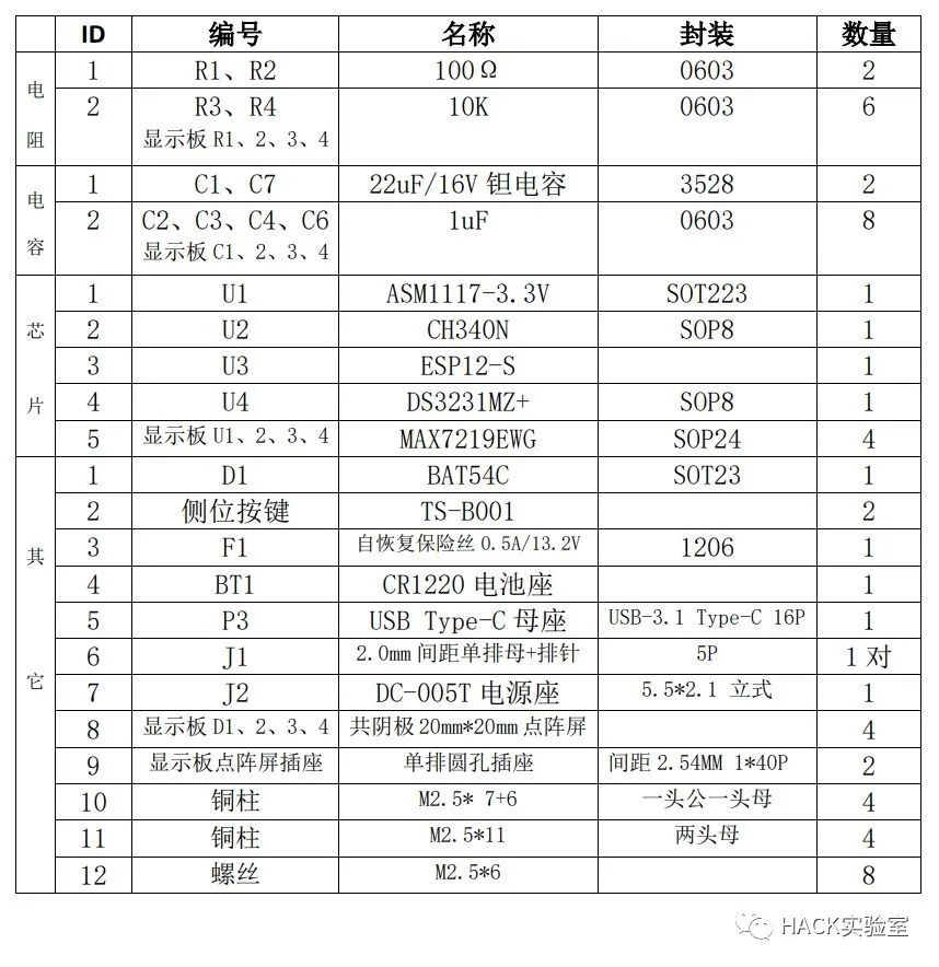
After receiving the PCB, the next step is to purchase components and solder them. The main purpose of this upgrade over the previous version is to reduce the soldering difficulty. For example, I have tried to change all components to more easily solderable packages and reduce the number of components. To make it easier for everyone to create, I have also organized the BOM as follows.

The hardware soldering for this project can be said to be very simple. The only slightly difficult part is the soldering of the USB female socket, where you need to be careful to avoid short circuits.

Once we have completed the hardware soldering and production, we can download the program. In the data package, you can see the firmware folder, which contains the software program for this clock, written using the Arduino IDE.After connecting the clock hardware to the computer via USB, you need to install the driver first. We are using the CH340N from Nanjing Qinheng Microelectronics, and you can directly go to their official website to download and install it.
Once everything is ready, you can compile it and install the corresponding library files as prompted. In Tools–Port, select the COM port where our board is located, press and hold the Download button on our board, then press the Reset button briefly, and release both hands to enter download mode. At this point, click Upload in the IDE, and once the progress bar is complete, the download is finished.
 Just download and install it.
Taking Apple as an example, first connect to the environment’s 2.4G Wi-Fi, then open the software and enter the Wi-Fi password in the Password field.

Then power on the matrix clock, and the clock will display “Wi-Fi”. At this point, the clock is connecting to the Wi-Fi information set inside. The first time you use it, since the Wi-Fi information has not been set, it will flash “Err!!” once after a few seconds indicating a connection failure and then display “S-con” to enter configuration mode. At this point, take out your prepared phone, click “Confirm” and wait. A few seconds later, it will display “OK!!”, and the network configuration is successful! Once the network is configured, if the router information does not change, you will not need to configure it again, and the clock will automatically connect when powered on.
PS. I will be making another clock soon, so stay tuned~

「Creation is not easy」
I hope everyone will like and support me by clicking “Like” + “See”. Your support is my greatest encouragement, and it is also the motivation for me to continue creating.

HACK Laboratory
DIY Closed-loop Control of Stepper Motor (Open Source)
One Article to Explain I2C Bus Protocol Thoroughly
The Story of Fairchild Semiconductor
DIY a MINI Game Console
See if an Article Can Thoroughly Explain “Impedance Matching”
In-depth Analysis of STM32 Microcontroller I/O Working Modes
Share Several Common Level Conversion Solutions
Temperature Sensors I Have Used Over the Years
DIY High-Precision Low-Cost Hardcore Desktop Clock
Why I Use KiCad as My Main EDA Software