Source: https://juejin.cn/user/3931509313252552/postse
In communication and IT work, networking is essential, and the most important protocol in the network is TCP. Whether in actual work or in written exams and interviews, you can’t escape TCP.
I have read documents related to TCP in the RFC, examined the source code related to TCP in Linux, and looked at various frameworks containing TCP code, so I have a bit of a grasp on TCP.
I have always wanted to find time to share knowledge related to TCP. If anyone has questions, feel free to discuss. In fact, once you understand TCP, you realize it’s not that complicated. All that TCP/IP network knowledge!
Consider the simplest case: communication between two hosts. At this point, you only need a network cable to connect them, specifying their hardware interfaces, such as using USB, 10V voltage, 2.4GHz frequency, etc. This layer is the Physical Layer, and these specifications are the Physical Layer Protocol.
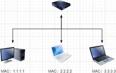
Of course, we are not satisfied with just connecting two computers, so we can use a switch to connect multiple computers, as shown below:
This connected network is called a local area network (LAN), which can also be referred to as Ethernet (Ethernet is a type of LAN). In this network, we need to identify each machine so that we can specify which machine to communicate with. This identifier is the hardware address MAC. The hardware address is determined when the machine is manufactured and is permanently unique. In a LAN, when we need to communicate with another machine, we only need to know its hardware address, and the switch will send our message to the corresponding machine.
Here we can ignore how the lower-level cable interfaces send data and abstract the physical layer, creating a new layer above it, which is the Data Link Layer.
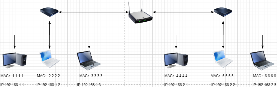
We are still not satisfied with the scale of the LAN and need to connect all the LANs together, which requires using routers to connect two LANs:
However, if we still use hardware addresses as the unique identifier for communication objects, it becomes impractical to remember all the hardware addresses as the network scales. At the same time, a network object may frequently change devices, making the maintenance of the hardware address table even more complex. Here, a new address is used to mark a network object: IP Address.
To understand the IP address through a simple mailing example.
I live in Beijing, and my friend A lives in Shanghai. I want to send a letter to friend A:
-
After writing the letter, I will write my friend A’s address on it and drop it at the Beijing post office (adding the target IP address and sending it to the router).
-
The post office will help me transport the letter to the local Shanghai post office (the information will be routed to the router of the target IP’s LAN).
-
The local router in Shanghai will help me deliver the letter to friend A (communication within the LAN).
Therefore, here the IP address is a network access address (friend A’s address), and I only need to know the target IP address for the router to bring the message to me. In a LAN, a dynamic relationship can be maintained between a MAC address and an IP address, allowing us to find the MAC address of a machine based on the destination IP address for sending.
This way, we don’t need to manage how to select machines at the lower level; we only need to know the IP address to communicate with our target. This layer is the Network Layer. The core function of the Network Layer is to provide logical communication between hosts. In this way, all hosts in the network are logically connected, and the upper layer only needs to provide the target IP address and data, and the Network Layer can send the message to the corresponding host.
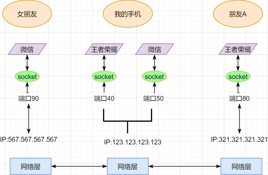
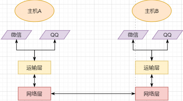
A host can have multiple processes, and different network communications can occur between processes, such as playing games with friends while chatting with a girlfriend. My phone communicates simultaneously with two different machines. So when my phone receives data, how does it distinguish whether the data is from WeChat or from the game? Therefore, we must add another layer above the Network Layer: Transport Layer:
The Transport Layer uses sockets to further split network information so that different application processes can independently make network requests without interfering with each other. This is the essence of the Transport Layer: providing logical communication between processes. Here, the processes can be between hosts or within the same host, so socket communication in Android is also a form of inter-process communication.
Now that application processes on different machines can communicate independently, we can develop various applications on the computer network, such as web page HTTP, file transfer FTP, etc. This layer is called the Application Layer.
The Application Layer can also be further divided into Presentation Layer and Session Layer, but their essential characteristics remain unchanged: fulfilling specific business needs. Compared to the four layers below, they are not mandatory and can be classified within the Application Layer.
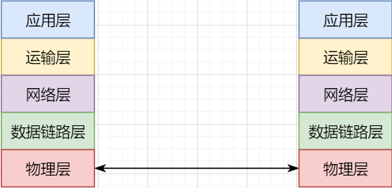
Finally, let’s summarize the layers of the network: detailed explanation of network protocols with illustrations.
-
The lowest layer, the Physical Layer, is responsible for direct communication between two machines through hardware;
-
The Data Link Layer uses hardware addresses for addressing within the LAN, achieving LAN communication;
-
The Network Layer achieves logical communication between hosts through abstract IP addresses;
-
The Transport Layer, based on the Network Layer, splits data to achieve independent network communication between application processes;
-
The Application Layer develops various functions based on the Transport Layer according to specific needs.
It is important to note that layering is not a physical separation but a logical separation. By encapsulating the underlying logic, the upper layer can directly rely on the functions of the lower layer without worrying about the specific implementation, simplifying development.
This layered thinking is also the responsibility chain design pattern, which encapsulates different responsibilities layer by layer, making development and maintenance easier. The interceptor design pattern in OkHttp is also this kind of responsibility chain model.
This article mainly explains TCP, and here we need to add some knowledge about the Transport Layer.
Essence: Providing Process Communication
In the Network Layer below the Transport Layer, it does not know which process the data packet belongs to; it only handles the reception and sending of data packets. The Transport Layer is responsible for receiving data from different processes and handing it to the Network Layer while splitting the data from the Network Layer to different processes. The process of gathering data to the Network Layer is called multiplexing, while the process of splitting data from the Network Layer is called demultiplexing.
The performance of the Transport Layer is limited by the Network Layer. This is easy to understand; the Network Layer provides the underlying support for the Transport Layer. Therefore, the Transport Layer cannot decide its bandwidth, delay, and other upper limits. However, it can develop more features based on the Network Layer, such as reliable transmission. The Network Layer is only responsible for trying to send data packets from one end to the other without guaranteeing that the data can arrive and be complete.
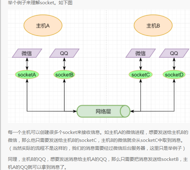
Bottom Layer Implementation: Socket
As mentioned earlier, the simplest Transport Layer protocol is to provide independent communication between processes, but the underlying implementation is independent communication between sockets. In the Network Layer, the IP address is a logical address of a host, while in the Transport Layer, the socket is a logical address of a process; of course, a process can have multiple sockets. Application processes can listen on sockets to receive messages sent to those sockets.
A socket is not a tangible object but an abstraction created by the Transport Layer. The Transport Layer introduces the concept of ports to distinguish different sockets. A port can be understood as a network communication port on a host, each with a port number; the number of ports is determined by the Transport Layer protocol.
Different Transport Layer protocols define sockets in different ways. In the UDP protocol, a socket is defined using the target IP + target port number; in TCP, it is defined using the target IP + target port number + source IP + source port number. We only need to attach this information to the header of the Transport Layer message, and the target host will know which socket we want to send to, allowing the corresponding process listening on that socket to receive the information.
Transport Layer Protocol
The protocols of the Transport Layer are the well-known TCP and UDP. Among them, UDP is the most minimal Transport Layer protocol, only implementing inter-process communication; while TCP builds on UDP to implement reliable transmission, flow control, congestion control, connection-oriented features, and is also more complex.
Of course, in addition to these, there are many other excellent Transport Layer protocols, but the most widely used are TCP and UDP. UDP will also be summarized later.
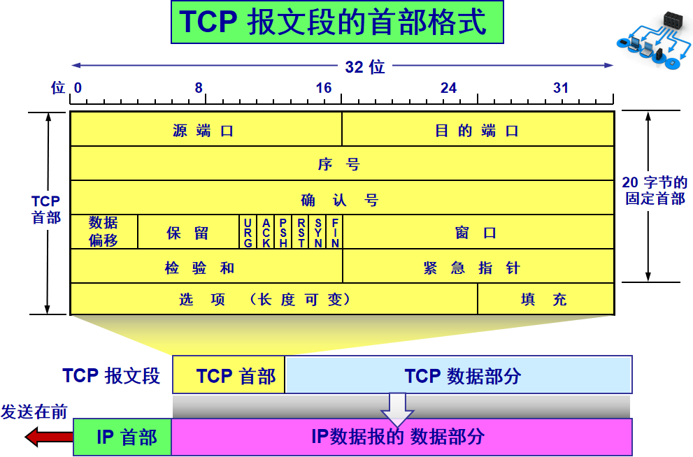
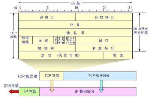
The TCP protocol, reflected in the message, adds a TCP header before the data transmitted from the Application Layer. This header contains TCP information. First, let’s look at the overall structure of this header:
This image is from a university teacher’s presentation, which is very useful for study. The bottom part shows the relationships between messages; the TCP data part is the data transmitted from the Application Layer.
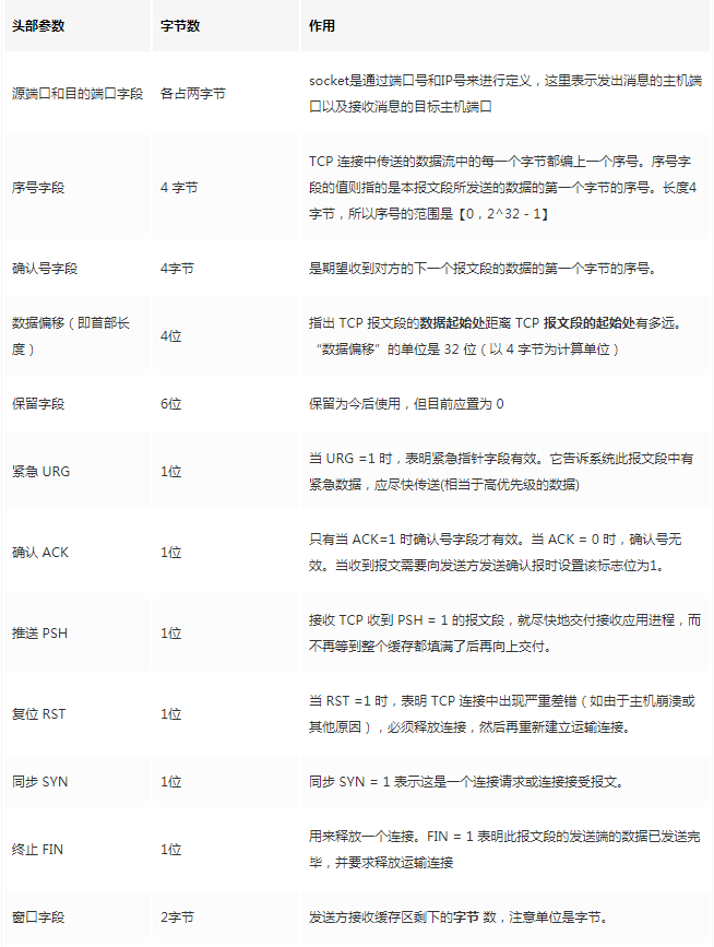
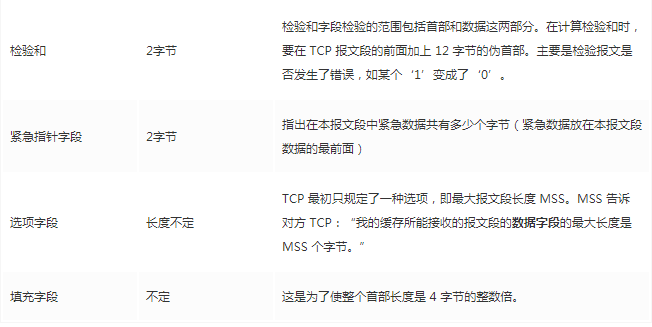
The fixed length of the TCP header is 20 bytes, with an additional 4 bytes being optional. There is a lot of content, but some familiar items include: source port, destination port. Wait? Isn’t the socket still required to use IP for positioning? The IP address is added at the Network Layer. Other contents will be gradually explained later. As a summary article, here is a reference table for review:
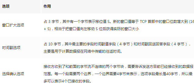
The options field contains the following other options:
After discussing the content below, you will be familiar with these fields.
/ TCP Byte Stream Feature /
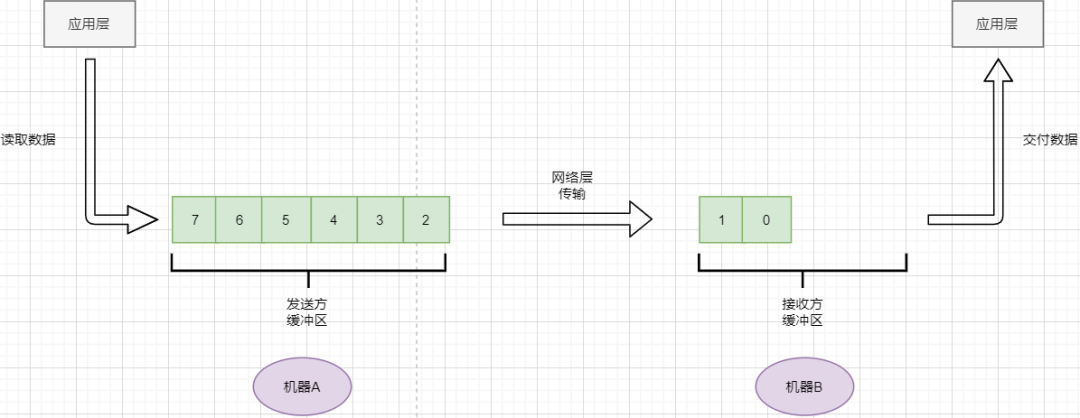
TCP does not simply add headers to the data transmitted from the Application Layer and send it to the target; it treats the data as a byte stream, numbering them before sending them in parts. This is the byte stream-oriented feature of TCP:
-
TCP reads data from the Application Layer in a stream and stores it in its sending buffer, while numbering these bytes.
-
TCP selects an appropriate amount of bytes from the sender’s buffer to form a TCP message and sends it to the target through the Network Layer.
-
The target reads the bytes and stores them in its receiving buffer, delivering them to the Application Layer at the appropriate time.
The byte stream feature allows for not having to store excessively large data at once, which would occupy too much memory. The downside is that it cannot know the meaning of these bytes. For example, when the Application Layer sends an audio file and a text file, to TCP, it is just a string of bytes with no meaning, which can lead to packet sticking and unpacking issues, which will be discussed later.
/ Reliable Transmission Principle /
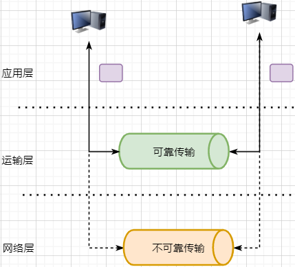
Previously mentioned, TCP is a reliable transmission protocol, meaning that any data handed to it will definitely be sent to the target address correctly, unless the network crashes. It implements the following network model:
For the Application Layer, it serves as a reliable transmission support service; while the Transport Layer relies on the unreliable transmission of the Network Layer. Although protocols can be used at the Network Layer or even the Data Link Layer to ensure the reliability of data transmission, this would make the network’s design more complex and reduce efficiency. It is more appropriate to place the guarantee of data transmission reliability at the Transport Layer.
Key points of the reliable transmission principle include: sliding window, timeout retransmission, cumulative acknowledgment, selective acknowledgment, continuous ARQ.
Stop-and-Wait Protocol
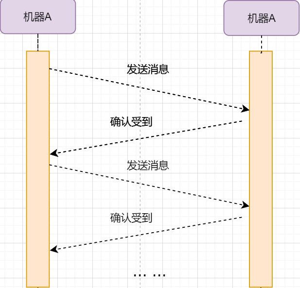
The simplest method to achieve reliable transmission is: I send a data packet to you, and then you reply to me that you received it, and I continue to send the next data packet. The transmission model is as follows:
This “one request and one reply” method to ensure reliable transmission is called the stop-and-wait protocol. I wonder if you remember that earlier the TCP header has an ack field, which, when set to 1, indicates that this message is a confirmation receipt.
Now let’s consider a situation: packet loss. The unreliable network environment can lead to data packets being lost during transmission. If machine A sends a data packet that gets lost, machine B will never receive it, and machine A will be left waiting indefinitely. The solution to this problem is: timeout retransmission. When machine A sends a data packet, it starts a timer; if the time expires without receiving a confirmation reply, it can be assumed that packet loss has occurred, and it will resend, which is the retransmission.
However, retransmission can lead to another problem: if the original data packet was not lost but just took longer to arrive in the network, then machine B will receive two data packets. How does machine B distinguish whether these two data packets are from the same data or different data? This requires the previously mentioned method: numbering the data bytes. This way, the receiving end can determine based on the byte numbering whether the data is new or a retransmission.
In the TCP header, there are two fields: sequence number and acknowledgment number, which indicate the number of the first byte of data sent by the sender and the number of the first byte of data expected by the receiver. As previously mentioned, TCP is byte stream-oriented, but it does not send one byte at a time; instead, it takes a whole segment at once. The length of the segment is influenced by various factors, such as the size of the buffer and the frame size limits of the Data Link Layer, etc.
Continuous ARQ Protocol
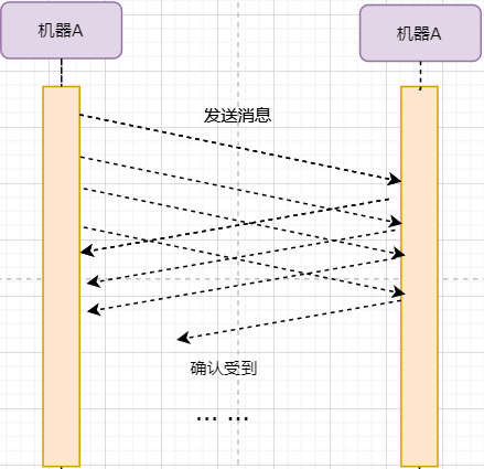
The stop-and-wait protocol can meet the needs of reliable transmission, but it has a fatal flaw: inefficiency. After the sender sends a data packet, it enters a waiting state, during which it does nothing, wasting resources. The solution is to continuously send data packets. The model is as follows:
The biggest difference from stop-and-wait is that it continuously sends data, and the receiver continuously receives data and acknowledges it one by one. This greatly increases efficiency. However, it also brings some additional problems:
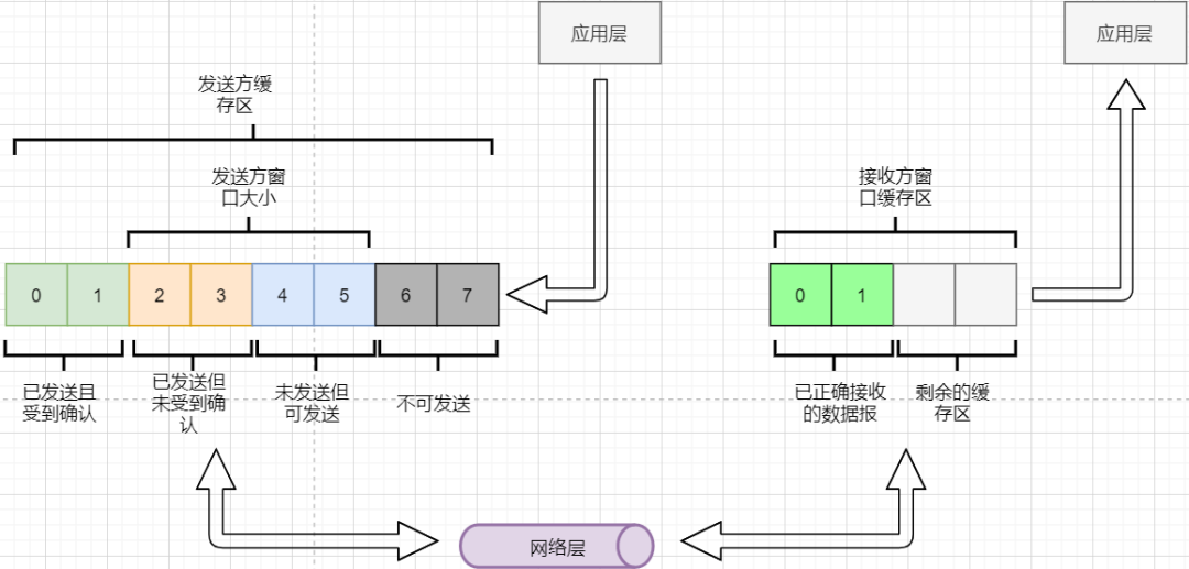
Can the sender send indefinitely until all data in the buffer is sent? No, because it needs to consider the receiving end’s buffer and data reading capacity. If the sender sends too fast and the receiver cannot accept it, it will only lead to frequent retransmissions, wasting network resources. Therefore, the sending range of the sender needs to consider the receiving end’s buffer. This is the flow control of TCP. The solution is the sliding window. The basic model is as follows:
-
The sender needs to set its own sendable window size based on the receiver’s buffer size, where data within the window is sendable, and data outside the window is not sendable.
-
When the data within the window receives confirmation replies, the entire window moves forward until all data is sent.
In the TCP header, there is a window size field that indicates the remaining buffer size of the receiver, allowing the sender to adjust its sending window size. Through the sliding window, TCP can implement flow control to prevent sending too fast, leading to excessive data loss.
Continuous ARQ brings a second problem: the network is filled with acknowledgment packets equal to the amount of data packets being sent, because every data packet sent must have an acknowledgment. The method to improve network efficiency is: cumulative acknowledgment. The receiver does not need to reply to each one but can inform the sender that all data packets before a certain point have been received after accumulating a certain amount of data. For example, if it receives 1234, the receiver only needs to tell the sender that it received 4, so the sender knows that 1234 has all been received.
The third problem is: how to handle packet loss. In the stop-and-wait protocol, it is simple; just a timeout retransmission solves it. However, in continuous ARQ, it is different. For example, if the receiver receives 123 and 567, with byte 4 lost. Following the cumulative acknowledgment logic, it can only send back acknowledgment for 3, and 567 must be discarded because the sender will retransmit. This is the GBN (Go-Back-N) approach.
But we find that only retransmitting 4 is sufficient, which is a waste of resources, so there is the Selective Acknowledgment (SACK). In the options field of the TCP message, it can specify the segments that have already been received. Each segment needs two boundaries to be determined. This way, the sender can retransmit only the lost data based on this options field.
Summary of Reliable Transmission
At this point, the principles of TCP’s reliable transmission have been mostly introduced. Let’s summarize:
-
Guaranteeing that every data packet reaches the receiver through continuous ARQ protocols and the send-acknowledgment model.
-
Using byte numbering to label whether each data is a retransmission or new data.
-
Using timeout retransmission to address the issue of data packets being lost on the network.
-
Implementing flow control through sliding windows.
-
Improving acknowledgment and retransmission efficiency through cumulative acknowledgment and selective acknowledgment.
Of course, this is just the tip of the iceberg regarding reliable transmission; if interested, you can delve deeper into research (which is similar to chatting with the interviewer [dog head]).
Congestion control considers another issue: avoiding excessive network congestion leading to severe packet loss and reduced network efficiency.
Let’s take a real-world traffic example:
The number of cars that can travel on a highway at the same time is limited. During holidays, severe traffic jams occur. In TCP, when data packets timeout, retransmission occurs, leading to more cars coming in, which causes further congestion and ultimately results in: packet loss – retransmission – packet loss – retransmission. Eventually, the entire network collapses.
The congestion control here is not the same as flow control; flow control is a means of congestion control: to avoid congestion, the flow must be controlled. The goal of congestion control is to limit the amount of data sent by each host to prevent network efficiency from declining. This is similar to restricting vehicle movement based on license plate numbers in cities like Guangzhou. Otherwise, everyone will be stuck on the road, and no one can move.
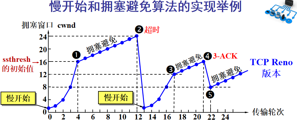
The key points of congestion control include: slow start, fast recovery, fast retransmission, and congestion avoidance. Here, I will again sacrifice a university teacher’s PPT image:
The Y-axis represents the sender’s window size, and the X-axis represents the number of rounds sent (not byte numbers).
-
At the beginning, the window is set to a small value, then doubles every round. This is the slow start.
-
When the window value reaches the ssthresh value, which is a limit set based on real-time network conditions, it enters congestion avoidance, increasing the window value by 1 each round to gradually probe the network’s limits.
-
If data timeouts occur, it indicates a high likelihood of congestion, and it returns to slow start, repeating the previous steps.
-
If three identical acknowledgment replies are received, it indicates that the network is not performing well, and the ssthresh value is set to half of its original value, continuing with congestion avoidance. This part is called fast recovery.
-
If packet loss information is received, the lost packet should be retransmitted as quickly as possible, which is fast retransmission.
-
Of course, the upper limit of the window cannot rise indefinitely; it cannot exceed the size of the receiver’s buffer.
Through this algorithm, we can largely avoid network congestion.
Additionally, we can inform the sender when the router is about to be full, rather than waiting for a timeout to handle it, which is Active Queue Management (AQM). There are many other methods, but the algorithms above are key.
This section discusses the well-known TCP three-way handshake and four-way handshake, and with the previous content, this section should be easy to understand.
TCP is connection-oriented, but what is a connection? The connection here is not a physical connection but a record between the two communicating parties. TCP is a full-duplex communication, which means data can be sent back and forth, so both parties need to record each other’s information. According to the previous principles of reliable transmission, both parties in a TCP communication need to prepare a receiving buffer to receive each other’s data, remember each other’s sockets to know how to send data, and remember each other’s buffers to adjust their window sizes, etc. These records constitute a connection.
In the Transport Layer section, it was mentioned that the address for communication between Transport Layer parties is defined using sockets, and TCP is no exception. Each TCP connection can only have two objects, meaning two sockets, and cannot have three. Therefore, the definition of a socket requires four key factors: source IP, source port number, target IP, and target port number to avoid confusion.
If TCP only used target IP + target port number to define sockets like UDP, it would lead to multiple senders sending to the same target socket simultaneously. In this case, TCP would not be able to distinguish whether the data came from different senders, leading to errors.
Since it is a connection, there are two key points: establishing a connection and disconnecting a connection.
Establishing a Connection
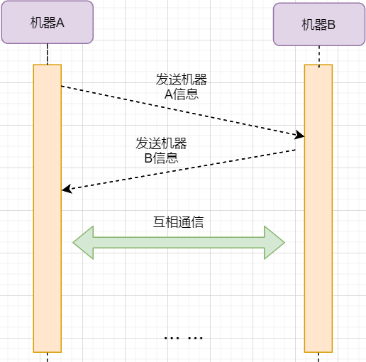
The purpose of establishing a connection is to exchange information and remember each other’s information. Therefore, both parties need to send their information to each other:
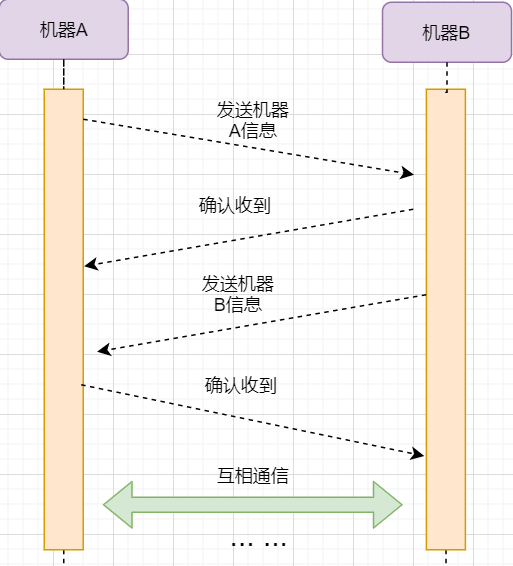
However, the reliable transmission principle tells us that data transmission over the network is unreliable, and we need a confirmation reply from the other party to ensure that the message has arrived correctly. As shown in the figure below:
The acknowledgment of machine B and the information sent from machine B can be combined, reducing the number of messages; moreover, sending machine B’s message to machine A itself represents that machine B has already received the message. Therefore, the final example figure is:
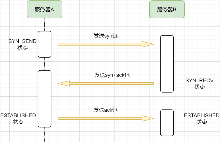
The steps are as follows:
-
Machine A sends a SYN packet to machine B requesting to establish a TCP connection, attaching its receiving buffer information, and enters the SYN_SEND state, indicating that the request has been sent and is waiting for a reply;
-
Machine B receives the request, records the information from machine A, creates its own receiving buffer, and sends a SYN+ACK combined packet back to machine A, while entering the SYN_RECV state, indicating that it is ready and waiting for machine A’s reply to send data to A;
-
Machine A receives the reply, records machine B’s information, and sends an ACK message, entering the ESTABLISHED state, indicating that it is fully prepared to send and receive;
-
Machine B receives the ACK data and enters the ESTABLISHED state.
The sending of three messages is called the three-way handshake.
Disconnecting a Connection
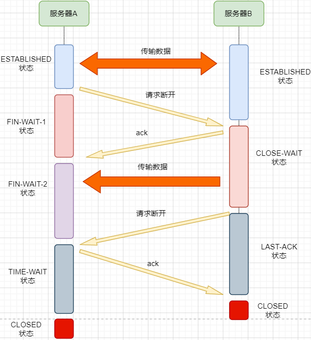
Disconnecting a connection is similar to the three-way handshake; let’s go straight to the image:
1. After machine A finishes sending data, it requests machine B to disconnect, entering the FIN_WAIT_1 state, indicating that data transmission has been completed and a FIN packet has been sent (the FIN flag is set to 1);
2. Machine B receives the FIN packet and replies with an ACK packet indicating it has received it, but machine B may still have data that has not been sent; it enters the CLOSE_WAIT state, indicating that the other party has completed sending and requested to close the connection, and it can close the connection after completing its own data transmission;
3. After machine B finishes sending its data, it sends a FIN packet to machine A, entering the LAST_ACK state, indicating it is waiting for an ACK packet to close the connection;
4. Machine A receives the FIN packet, knowing that machine B has also completed sending, replies with an ACK packet, and enters the TIME_WAIT state.
The TIME_WAIT state is special. When machine A receives machine B’s FIN packet, ideally, it can directly close the connection; however:
-
We know that the network is unstable, and some data sent by machine B may not have arrived yet (slower than the FIN packet);
-
At the same time, the ACK packet sent may be lost, and machine B will retransmit the FIN packet;
If machine A closes the connection immediately, it will lead to incomplete data and machine B being unable to release the connection. Therefore, machine A needs to wait for the maximum lifespan of two packets to ensure that no residual packets are left in the network before closing the connection.
5. Finally, after waiting for the maximum lifespan of two packets, machine B receives the ACK message, and both machines close the connection, entering the CLOSED state.
The process of sending four messages to disconnect the connection is called the four-way handshake.
Now, the reasons for why the handshake is three times and the disconnection is four times, whether it must be three/four times, and why to wait for 2MSL before closing the connection, etc., are all resolved.
In addition to TCP, the Transport Layer protocol also includes the well-known UDP. If TCP stands out for its comprehensive and stable features, then UDP is the minimalist approach that can be chaotic.
UDP only implements the minimal functionality of the Transport Layer: inter-process communication. For the data transmitted from the Application Layer, UDP simply adds a header and directly hands it over to the Network Layer. The UDP header is very simple, containing only three parts:
-
Source port, destination port: port numbers are used to distinguish different processes on the host.
-
Checksum: used to verify that the data packet has not encountered errors during transmission, such as a 1 changing to a 0.
-
Length: the length of the message.
Therefore, UDP has only two functions: verifying whether the data packet has errors and distinguishing different process communications.
However, although TCP has many functions, it also comes with corresponding costs. For example, the connection-oriented feature incurs overhead during connection establishment and disconnection; the congestion control feature limits the transmission upper limit, etc. Below are the advantages and disadvantages of UDP:
Disadvantages of UDP
-
Cannot guarantee that messages arrive complete and correctly; UDP is an unreliable transmission protocol;
-
Lacks congestion control, easily competing for resources and leading to network system paralysis.
Advantages of UDP
-
Faster efficiency; no need for connection establishment and congestion control.
-
Can connect to more clients; no connection state, no need to create buffers for each client.
-
Smaller header bytes, lower overhead; the fixed header of TCP is 20 bytes, while UDP is only 8 bytes; a smaller header means a larger proportion of data.
-
In scenarios requiring high efficiency with allowable errors, such as live broadcasting, it does not need to guarantee that every data packet arrives intact; a certain packet loss rate is acceptable, making the efficient UDP a more suitable choice.
-
Can perform broadcasting; UDP is not connection-oriented, so it can send messages to multiple processes simultaneously.
UDP Applicable Scenarios
UDP is suitable for scenarios requiring high customization of the transmission model, allowing packet loss, requiring high efficiency, and needing broadcasting; for example:
Chunked Transmission
We can see that the Transport Layer does not simply add a header to the entire data packet and send it directly; it splits it into multiple messages for separate transmission. Why does it do this?
Readers might think: the Data Link Layer limits the data length to only 1460. Why does the Data Link Layer impose such a restriction? The fundamental reason is that the network is unstable. If the message is too long, it is highly likely that it may suddenly interrupt during transmission, requiring the entire data to be retransmitted, thus reducing efficiency. By splitting data into multiple packets, if a certain data packet is lost, only that packet needs to be retransmitted.
But does splitting it into smaller chunks make it better? If the length of the data field in the message is too low, it will make the header proportion too large, causing the header to become the biggest burden in network transmission. For example, if the data is 1000 bytes, and each message header is 40 bytes, if split into 10 messages, it requires 400 bytes of header transmission; however, if split into 1000 messages, it would require 40000 bytes of header transmission, drastically reducing efficiency.
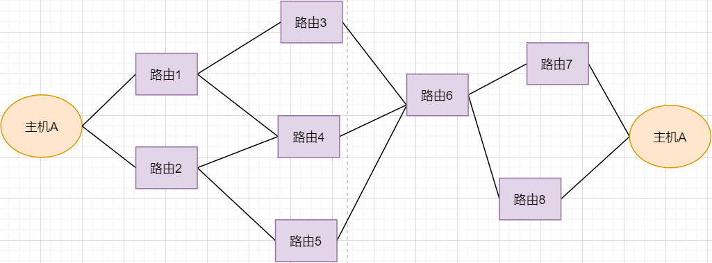
Routing Transformation
First, let’s look at the image:
-
Under normal circumstances, the data packet from host A can be transmitted through paths 1-3-6-7.
-
If router 3 fails, it can be transmitted through 1-4-6-7.
-
If router 4 also fails, it can only be transmitted through 2-5-6-7.
-
If router 5 fails, the line will be interrupted.
Using routing forwarding improves the fault tolerance of the network. The fundamental reason is still that the network is unstable. Even if several routers fail, the network can still function. However, if the core router fails, it directly prevents communication between host A and host B, so it is necessary to avoid such core routers.
Another benefit of using routing is load balancing. If one line is too congested, it can be transmitted through another route to improve efficiency.
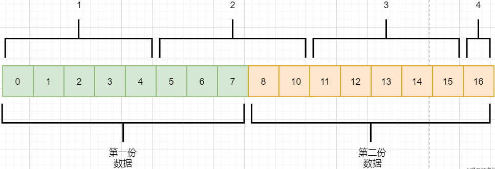
Packet Sticking and Unpacking
As mentioned in the byte stream-oriented section, TCP does not understand the meaning of these data streams; it only knows to take the data stream from the Application Layer, cut it into packets, and send them to the target object. If the Application Layer transmits two data packets, it is likely to produce the following situation:
-
The Application Layer needs to send two pieces of data to the target process, one audio and one text.
-
TCP only knows that it has received a stream and splits it into four segments for sending.
-
The data in the second message may mix data from both files, leading to packet sticking.
-
The target process in the Application Layer, upon receiving the data, needs to split this data into the correct two files, which is unpacking.
Packet sticking and unpacking are issues that the Application Layer needs to solve. It can append special bytes at the end of each file, such as newline characters; or control each message to contain only one file’s data, padding with 0s if insufficient, etc.
Malicious Attacks
The connection-oriented nature of TCP can be exploited by malicious individuals to attack servers.
As previously discussed, when we send a SYN packet to a host to request a connection, the server creates a buffer for us and returns a SYN+ACK message. If we spoof the IP and port and send a massive number of requests to a server, it will create a large number of half-open TCP connections, making it unable to respond normally to user requests, leading to server paralysis.
Solutions can include limiting the number of connections created by an IP, allowing half-open TCP connections to close themselves in a shorter time, and delaying the allocation of memory for the receiving buffer, etc.
Long Connections
Every request to the server requires creating a TCP connection, which is closed after the server returns data. If there are a large number of requests in a short time, frequently creating and closing TCP connections is resource-wasting behavior. Therefore, we can keep the TCP connection open during this period for requests to improve efficiency.
It is necessary to note the maintenance time and creation conditions of long connections to avoid malicious exploitation that creates a large number of long connections, depleting server resources.
In the past, when I was learning, I felt that these things seemed useless, seemingly just for exams. In fact, when not applied, it is difficult to have a deeper understanding of this knowledge. For example, now when I look at the above summary, much of it is only surface recognition, not knowing the true meaning behind it.
However, as I learn more broadly and deeply, I will have a deeper understanding of this knowledge. There are moments when I realize: oh, that thing is used this way, that thing is like this, and learning is genuinely useful.
Now, perhaps after learning, one may not feel much, but when applied or learned in related contexts, there will be an enlightening sensation, yielding significant insights.
Click “Read Original” to join [Communication Encyclopedia * Knowledge Planet] and download a wealth of professional documents.
1. SPN and PTN Super Controller Technical Specifications.pdf 2. Computer Network Basics Lecture Notes (1400 pages).pptx 3. SDN Basic Training Courseware.ppt
4. Principles of Switches and Routers.pdf
5. Communication Principles.pdf
6. TCP/IP Principles.pdf
7. IP Network Slicing Technology.doc 8. SPN Overall Technical Requirements.pdf 9. SPN Network Architecture and Technical System.pptx
10. Huawei Switch: Router Advanced Training Materials.pdf
Give a “Collect + Like + View” triple click below 👇