Definition of Temperature Sensors
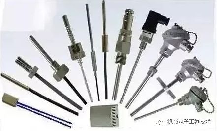
A temperature sensor refers to a sensor that can sense temperature and convert it into a usable output signal. Temperature sensors are the core part of temperature measuring instruments and come in a wide variety. They are very accurate in measuring environmental temperature and are widely used in agriculture, industry, workshops, warehouses, and other fields.
History of Temperature Sensors
In 1600 AD, Galileo invented the gas thermometer. A hundred years later, the liquid-in-glass thermometer and mercury thermometer were developed. With the needs of modern industrial technology, metal wire resistors, thermoelectric components, and bimetallic temperature sensors were subsequently developed. After 1950, semiconductor thermistors were developed. Recently, with the rapid development of raw materials and processing technology, various types of temperature sensors have been continuously developed.
Classification of Temperature Sensors
According to the measurement method, they can be divided into two main categories: contact and non-contact.
1. Contact Type
The detection part of contact temperature sensors is in good contact with the measured object, also known as thermometers.
Thermometers reach thermal equilibrium through conduction or convection, allowing the reading to directly represent the temperature of the measured object.
Generally, they have high measurement accuracy. Within a certain temperature range, thermometers can also measure the temperature distribution inside an object. However, for moving bodies, small targets, or objects with very low thermal mass, significant measurement errors may occur. Common thermometers include bimetallic thermometers, glass liquid thermometers, pressure thermometers, resistance temperature detectors, thermistors, and thermocouples. They are widely used in industries, agriculture, commerce, and in everyday life.
2. Non-Contact Type
Its sensitive element does not come into contact with the measured object, also known as non-contact temperature measuring instruments. These instruments can measure the surface temperature of moving objects, small targets, or objects with low thermal mass or rapid temperature changes (transient), and can also be used to measure the temperature distribution in a temperature field.
The most commonly used non-contact temperature measuring instruments are based on the fundamental laws of blackbody radiation, known as radiation thermometers. Various radiation measurement methods can only measure the corresponding luminous temperature, radiation temperature, or color temperature. Only the temperature measured for a blackbody (an object that absorbs all radiation and does not reflect light) is the true temperature. To determine the true temperature of an object, the emissivity of the material’s surface must be corrected. The emissivity of the material’s surface depends not only on temperature and wavelength but also on surface condition, coatings, and microstructure, making it difficult to measure accurately.
The advantage of non-contact temperature sensors is that the upper limit of measurement is not restricted by the temperature resistance of the sensing element, so there is no theoretical limit to the maximum measurable temperature.
According to the characteristics of sensor materials and electronic components, they can be divided into two categories: resistance thermometers and thermocouples.
1. Resistance Thermometers
Thermistors use semiconductor materials, mostly with a negative temperature coefficient, meaning that the resistance decreases as temperature increases.
Temperature changes cause significant changes in resistance, making it the most sensitive temperature sensor. However, thermistors have poor linearity and are greatly affected by the manufacturing process.
Thermistors also have their measurement techniques. The small size of thermistors is an advantage; they can stabilize quickly without causing thermal load. However, this also makes them less durable, and high current can cause self-heating. Since thermistors are resistive devices, any current source will cause heating due to power. Power equals the square of the current multiplied by the resistance. Therefore, a small current source should be used. If a thermistor is exposed to high heat, it will lead to permanent damage.
2. Thermocouples
Thermocouples are the most commonly used temperature sensors in temperature measurement. Their main advantages are a wide temperature range and adaptability to various atmospheric environments, as well as being sturdy, low-cost, and requiring no power supply, making them the cheapest option. Thermocouples are the simplest and most versatile temperature sensors, but they are not suitable for high-precision measurements and applications.
According to the output signal mode of temperature sensors, they can be roughly divided into three categories: digital temperature sensors, logic output temperature sensors, and analog temperature sensors.
1. Digital Temperature Sensors
These are silicon-based digital temperature sensors that use PTAT structures, which have good output characteristics related to temperature.
2. Logic Output Temperature Sensors
In many applications, we do not need to strictly measure temperature values but are only concerned whether the temperature exceeds a set range. Once the temperature exceeds the specified range, an alarm signal is issued to start or stop fans, air conditioners, heaters, or other control devices. Logic output temperature sensors can be selected for this purpose.
3. Analog Temperature Sensors
Common analog temperature sensors, such as thermocouples, thermistors, and RTDs, may have poor linearity in certain temperature ranges and require cold junction compensation or lead compensation; they have large thermal inertia and slow response times. Integrated analog temperature sensors, in comparison, have advantages such as high sensitivity, good linearity, and fast response speed, and they also integrate the driving circuit, signal processing circuit, and necessary logic control circuit into a single IC, making them compact and easy to use. Common analog temperature sensors include LM3911, LM335, LM45, AD22103 voltage output type, and AD590 current output type.
Working Principles of Temperature Sensors
1. Working Principle of Thermocouples
When two different conductors or semiconductors A and B form a loop and are connected at both ends, as long as the temperatures at the two junctions are different, with one end at temperature T (called the working end or hot end) and the other end at temperature TO (called the free end or cold end), a current is generated in the loop, and the electromotive force in the loop is called thermoelectric force. This phenomenon, where electromotive force is generated due to temperature differences, is called the Seebeck effect. There are two effects associated with the Seebeck effect: first, when current flows through the junction of two different conductors, heat is absorbed or released at this junction (depending on the direction of the current), called the Peltier effect; second, when current flows through a conductor with a temperature gradient, the conductor absorbs or releases heat (depending on the direction of the current relative to the temperature gradient), called the Thomson effect. The combination of two different conductors or semiconductors is known as a thermocouple.
2. Working Principle of Resistance Sensors
The resistance of a conductor changes with temperature. By measuring its resistance, the temperature of the measured object can be inferred. Sensors constructed using this principle are resistance temperature sensors, which are primarily used for temperature measurements in the range of -200 to 500℃. Pure metals are the main materials used to manufacture resistance thermometers, and the materials should have the following characteristics:
(1) The temperature coefficient of resistance should be large and stable, with a good linear relationship between resistance value and temperature.
(2) High resistivity, low thermal capacity, and fast response speed.
(3) Good reproducibility and processability, and low cost.
(4) Stable chemical and physical properties within the temperature measurement range.
Currently, platinum and copper are the most widely used materials in industry, and they have been made into standard temperature measuring resistance thermometers.
3. Infrared Temperature Sensors
In nature, when an object’s temperature is above absolute zero, it continuously radiates electromagnetic waves due to internal thermal motion, including infrared waves in the wavelength range of 0.75 to 100 μm. Infrared temperature sensors are made based on this principle.
4. Digital Temperature Sensors
These use silicon processes to produce digital temperature sensors that use PTAT structures, which have good output characteristics related to temperature. The PTAT output is modulated into a digital signal through a duty cycle comparator, and the relationship between duty cycle and temperature is as follows: DC=0.32 + 0.0047*t, where t is in degrees Celsius. The output digital signal is compatible with microcontroller MCUs, and through high-frequency sampling by the processor, the duty cycle of the output voltage square wave signal can be calculated to obtain the temperature. This temperature sensor has a resolution better than 0.005K due to its special process.
5. Logic Output Temperature Sensors
By setting a temperature range, once the temperature exceeds the specified range, an alarm signal is issued to start or stop fans, air conditioners, heaters, or other control devices. Logic output temperature sensors can be selected for this purpose. LM56, MAX6501-MAX6504, and MAX6509/6510 are typical representatives.
6. Analog Temperature Sensors
Common analog temperature sensors include LM3911, LM335, LM45, AD22103 voltage output type, and AD590 current output type.
AD590 is a current output temperature sensor from Analog Devices, Inc., with a supply voltage range of 3~30V and an output current of 223μA (-50℃) to 423μA (150℃), with a sensitivity of 1μA/℃. When a sampling resistor R is connected in series in the circuit, the voltage across R can be used as the output voltage. Note that the resistance value of R should not be too large to ensure that the voltage across AD590 is not less than 3V. The output current signal from AD590 can be transmitted over distances of more than 1 km. As a high-resistance current source, it can reach up to 20MΩ, so it does not need to consider the additional resistance introduced by selecting switches or CMOS multiplexers that may cause errors. It is suitable for multi-point temperature measurement and long-distance temperature measurement control.
Considerations When Selecting Temperature Sensors
1. The environmental conditions of the measured object may damage the temperature sensing element.
2. Whether the temperature of the measured object needs to be recorded, alarmed, and automatically controlled, and whether long-distance measurement and transmission are required.
3. In cases where the temperature of the measured object changes over time, whether the lag of the temperature sensing element can meet the measurement requirements.
4. The size of the temperature measurement range and accuracy requirements.
5. Whether the size of the temperature sensing element is appropriate.
6. Price considerations and ease of use.
How to Avoid Errors
When installing and using temperature sensors, the following errors should be avoided to ensure optimal measurement results.
1. Errors Introduced by Improper Installation
For example, the installation position and insertion depth of thermocouples may not reflect the true temperature of the furnace chamber. In other words, thermocouples should not be installed too close to doors or heating areas, and the insertion depth should be at least 8 to 10 times the diameter of the protection tube.
2. Thermal Resistance Errors
At high temperatures, if there is a layer of soot on the protection tube or dust adheres to it, thermal resistance increases, hindering heat conduction, causing the temperature reading to be lower than the true value of the measured temperature. Therefore, the exterior of the thermocouple protection tube should be kept clean to minimize errors.
3. Errors Introduced by Poor Insulation
If the thermocouple insulation is compromised, and dirt or salt residue between the protection tube and the lead plate causes poor insulation between the thermocouple and the furnace wall, this is especially severe at high temperatures. This can not only cause a loss of thermoelectric potential but also introduce interference, with errors sometimes reaching over a hundred degrees.
4. Errors Introduced by Thermal Inertia
Due to the thermal inertia of the thermocouple, the instrument’s indicated value lags behind the changes in the measured temperature, and this effect is particularly pronounced during rapid measurements. Therefore, thermocouples with thinner thermal electrodes and smaller protection tube diameters should be used whenever possible. If the measurement environment allows, the protection tube can even be removed. Due to the measurement lag, the amplitude of temperature fluctuations detected by the thermocouple is smaller than that of the furnace temperature fluctuations. The greater the measurement lag, the smaller the amplitude of thermocouple fluctuations, and the larger the discrepancy with the actual furnace temperature.

Want to know more
Quickly scan the code to follow us