The “Understanding at a Glance” series explains common terms and concepts of 8-bit MCUs in the most straightforward way.
Unlike traditional explanations of the 8051, this series will combine products and practices from mainstream microcontroller manufacturers in the current market (such as Zhongx, Shengx, Xinx, Yingx, Jiux, etc.) to analyze core knowledge in a simple and accessible manner.
By mastering these basic concepts, one can quickly get started with various related microcontrollers—the key is to build a solid foundation.
The input function is a fundamental module of the MCU, and its core concepts include Schmitt Trigger, internal pull-up/pull-down resistors, external interrupts, and keyboard interrupts. This article will introduce these topics.
Schmitt Trigger
The Schmitt Trigger, as a circuit that determines high and low levels for IO input, is essentially a technical term.
When we first encounter an MCU, we are usually told that 0V represents a low level and 5V represents a high level. So, how do we determine the voltage between 0V and 5V?This is where the Schmitt Trigger comes into play.
There are typically two options for the Schmitt Trigger: one is related to VDD, for example: 0.2VDD, 0.8VDD; the other is independent of VDD, for example: 0.8V, 2V.
In my observation, most Schmitt configurations on the market only provide threshold options related to VDD, which can be limiting in certain specific application scenarios.
Of course, there are almost no products on the market that do not support Schmitt Trigger. This is because without a Schmitt Trigger, when there is jitter in the input signal (even simple button bounce), it can lead to incorrect level detection, resulting in erroneous actions.
The most intuitive way to understand the characteristics of the Schmitt Trigger and the corresponding threshold levels is to look at the two diagrams below.
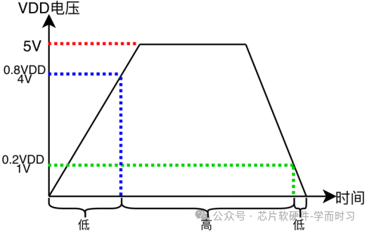
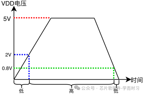
Let’s combine a common application:USB insertion check, to further understand the Schmitt Trigger and its level settings.
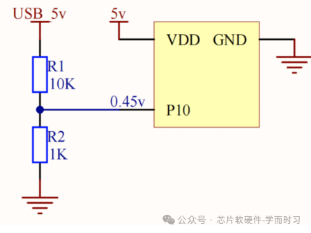
Situation A: The voltage at the voltage divider point is 0.45V. Regardless of whether the USB is connected or not, since 0.45V is far below the high-level threshold (2V or 4V (0.8VDD)), the MCU will always detect it as a low level, thus failing to effectively recognize the presence of the USB input signal.
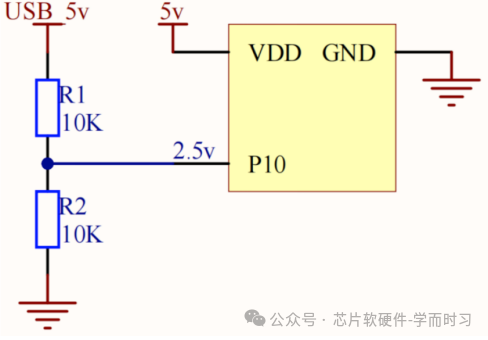
Situation B: The voltage at the voltage divider point is 2.5V. If using 0.2VDD/0.8VDD, i.e., 1V/4V, then it will only be determined as a high level when the input voltage exceeds 4V. However, the maximum voltage produced by this voltage divider is 2.5V, which is below 4V, failing to trigger a high level, causing the MCU to always detect it as a low level. Therefore, in this case, one can only choose 0.8V/2V. 2.5V is greater than 2V and can be stably determined as a high level.
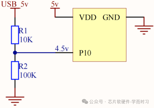
Situation C: The voltage at the voltage divider point is 4.5V. At this point: if choosing 0.8V/2V: 4.5V > 2V high threshold can be stably determined as a high level. If choosing 0.2VDD/0.8VDD, i.e., 1V/4V: 4.5V > 4V, it can also be stably determined as a high level. Therefore, at this voltage divider level, both Schmitt Trigger settings are applicable.

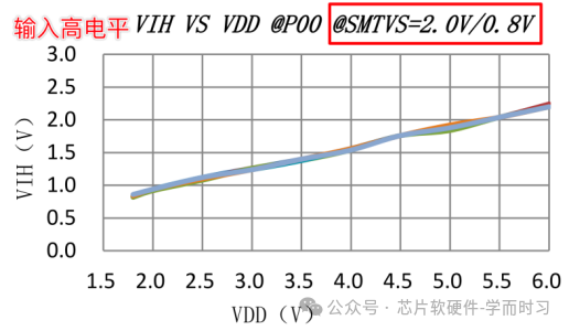
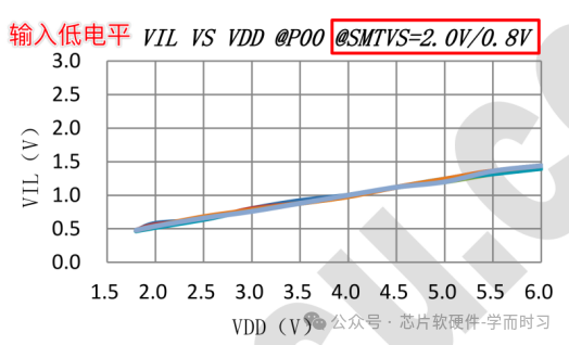
Careful readers will surely notice that the parameters in the electrical characteristics table seem to be inconsistent with the characteristic curves of the Schmitt Trigger. For example, when VDD=5V and choosing the 0.8V/2V setting, the characteristic curve shows that an input voltage of about 1.8V is determined as a high level, and about 1.3V is determined as a low level. This seems to contradict the selection.
This is because the meaning expressed by the electrical characteristics table is:
Taking VDD=5V and choosing the 0.8V/2V setting as an example,
-
When the input voltage ≥ 2.0V, the chip guarantees it will be recognized as a high level.
-
When the input voltage ≤ 0.8V, the chip guarantees it will be recognized as a low level.
Internal Pull-up/Pull-down Resistors

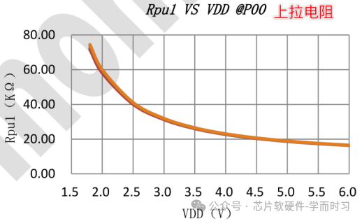
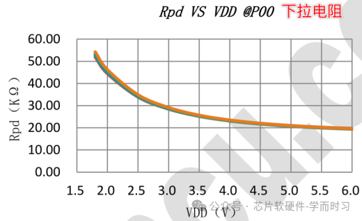
From the screenshots provided above, it can be observed that the typical resistance value of the internal resistor is 20kΩ, but this value will change with VDD. If the circuit has high precision requirements for this resistor, external resistors should be considered.
For I/O pins, if both pull-up and pull-down functions are enabled, and the resistance values of the pull-up and pull-down resistors are designed to be the same, then it can drive a 1/2 bias LCD screen.
When to Use External Resistors
Although the chip provides internal resistors, external resistors still have indispensable advantages in the following key scenarios:
1. Low Power Consumption Requirements
When configured as an internal pull-up (typical value 20kΩ) and the port is directly connected, under the condition of VDD=5V, the static leakage current during sleep is `5V / 20kΩ = 250uA`. For battery-powered devices that require long standby times, this power consumption is usually unacceptable during sleep.
Using an external high-resistance pull-up resistor (for example, 1MΩ). In this case, the leakage current drops to `5V / 1MΩ = 5μA`.
While using a large resistance external resistor (like 1MΩ) can effectively reduce static power consumption, it may also bring two challenges:
① The port leakage current generates an additional voltage drop across the large resistance, which may affect the stable recognition of high and low levels;
② Intermediate Level Power Consumption
The port leakage current is a semiconductor characteristic, and this parameter is not clearly indicated in the data sheets of all MCU manufacturers.
If you need further discussion, feel free to leave a message or send information through the public account.
2. High-Speed Signal Requirements (e.g., I2C Communication)
Internal pull-up resistors can achieve the basic communication function of I2C, but when the resistance is high, it leads to longer rise times, limiting communication speed. Typically, external pull-up resistors with smaller values, such as 1.5kΩ, 2.2kΩ, or 4.7kΩ, are needed to increase speed.
External Interrupts
External interrupts can detect interrupt signals generated by peripherals, such as buttons, UART decoding, USB input, etc.
They can be configured to trigger on rising edge, falling edge, or level change (i.e., triggering on both rising and falling edges).
The rising edge (or falling edge) trigger method generates an interrupt signal without needing to check whether the port is high or low again, improving operational efficiency.
Keyboard Interrupts
Keyboard interrupts only support level change triggers and can be understood as a type of external interrupt.
Although the name contains “keyboard”, the peripherals are not limited to buttons and can be any interrupt signal.
Input to Output, Output to Input
Since IO can output and input, its input-output functionality can be reused in applications. For example, the combination of LED scanning and button detection is commonly used in applications such as power banks and TWS.
This brings up a core question:When scanning LEDs with the IO configured as output, how long should one wait before switching to input mode for button detection to read the register state and determine high or low levels?
1. Output to Input
As long as the signal level on the port reaches (or exceeds) the effective level of the Schmitt Trigger, it can be correctly read.
In other words, the read operation itself is instantaneous, and whether it can be read correctly depends on whether the peripheral signal can timely reach the effective level.
Therefore, one can use an oscilloscope to measure the actual time required for the signal’s rising or falling edge to reach the effective level, and based on that, reserve a certain margin, which is the delay time required after switching from output to input. This means that this delay time is not a fixed standard value and should depend on the specific circuit.
2. Input to Output
The conversion itself takes effect immediately.
However, the actual output waveform (especially the rise/fall time) is influenced by the peripheral circuit, which may be close to ideal (steep edges) or relatively slow.
If you have any questions or suggestions, feel free to leave a message in the background of this public account.