First, let’s describe a few questions:
-
How do two I2C controllers communicate if they are connected on the same I2C bus?
-
With multiple devices connected to the I2C bus, how can we ensure that there are no data conflicts?
-
When multiple devices with the same address need to be connected to the same I2C bus, how can we avoid address conflicts?
-
What regulations exist for 7-bit and 10-bit addresses to ensure that addresses are not misidentified?
-
What is the situation with SMBus and PMBus related to I2C?
-
If the I2C bus hangs during use, how can it be recovered?
If you understand the above questions, this article will provide a deeper and more detailed exploration of the knowledge; if you do not understand, this document is just right for you.
1. Basic Characteristics of I2C:
1 Basic Characteristics
-
One data line (SDA) and one clock line (SCL);
-
Each device has a unique address; the controller provides the clock signal to control data transmission and reception;
-
Multiple controllers can be connected to the same bus; if multiple controllers send data simultaneously, an arbitration mechanism must be in place to ensure correct data transmission;
-
Serial synchronous bidirectional communication, Standard mode – 100 kbit/s, Fast mode – 400 kbit/s, Fast+ mode – 1 Mbit/s, High-speed mode – 3.4 Mbit/s;
-
Data transmission: Start flag + target address + write (0 bit) + write data + stop flag
-
Data reception: Start flag + target address + read (1 bit) + read data + stop flag
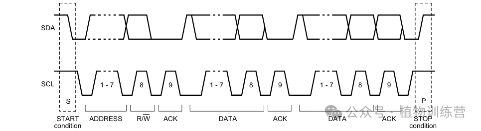
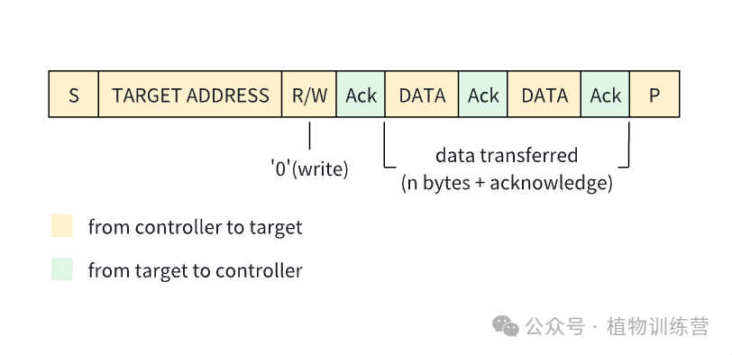
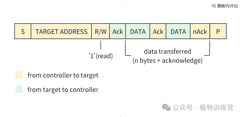
Note: The response for the last byte of read data is nAck, indicating that the slave device does not need to send more data.
2 I2C Actual Access Calls
For accessing I2C, the user-space implementation is as follows:
// User-space implementation
int main(int argc, char * argv[])
{
    int bus = argv[1];
    int deviceAddr = argv[2];

    // The parameter argv[1] specifies the I2C bus to access
    auto filename = std::format("/dev/i2c-{}", bus);

    // File IO can operate on regular files and device files, with no cached data
    int fd = open(filename.c_str(), O_RDWR);
    if (fd < 0)
    {
        filename = std::format("/dev/i2c/{}", bus);
        fd = open(filename.c_str(), O_RDWR);
    }

    if (fd < 0)
    {
        return -1;
    }

    // Read and write I2C
    struct i2c_rdwr_ioctl_data msgData;
    struct i2c_msg msg[2];

    // Send start flag and data
    msg[0].addr = deviceAddr;
    msg[0].flags = 0;
    msg[0].buf = txBuf; // Buffer for sending data
    msg[0].len = txLen; // Length of data to send

    // Resend start flag and receive data
    msg[0].addr = deviceAddr;
    msg[0].flags = I2C_M_RD;
    msg[0].buf = rxBuf; // Buffer for receiving data
    msg[0].len = rxLen; // Length of data to receive

    msgData.msgs = msg;
    msgData.nmsgs = 2;

    // #define I2C_RDWR    0x0707  /* Combined R/W transfer (one STOP only) */
    // #define I2C_SMBUS   0x0720  /* SMBus transfer */
    int ret = ioctl(fd, I2C_RDWR, &msgData);
    if (ret < 0)
    {
        return -1;
    }

    close(fd);
    fd = -1;
}
Kernel-space implementation:
/* This is the structure as used in the I2C_RDWR ioctl call */
struct i2c_rdwr_ioctl_data {
    struct i2c_msg __user *msgs;    /* pointers to i2c_msgs */
    __u32 nmsgs;            /* number of i2c_msgs */
};

struct i2c_msg {
    __u16 addr;
    __u16 flags;        // 0 means write  1 means read
#define I2C_M_RD        0x0001  /* guaranteed to be 0x0001! */
    __u16 len;
    __u8 *buf;
};

// ioctl() executes via system call - i2cdev_ioctl -- i2cdev_ioctl_rdwr -- i2c_transfer
int i2c_transfer(struct i2c_adapter *adap, struct i2c_msg *msgs, int num)
{
    ......
    if (do_bus_lock) {
        ret = __i2c_lock_bus_helper(adap);
        if (ret)
            return ret;
    }

    ret = __i2c_transfer(adap, msgs, num);
    if (do_bus_lock)
        i2c_unlock_bus(adap, I2C_LOCK_SEGMENT);
    ......
}

int __i2c_transfer(struct i2c_adapter *adap, struct i2c_msg *msgs, int num)
{
    ......
    for (ret = 0, try = 0; try <= adap->retries; try++) {
        if (i2c_in_atomic_xfer_mode() && adap->algo->master_xfer_atomic)
            ret = adap->algo->master_xfer_atomic(adap, msgs, num);
        else
            // The sending here is related to the specific chip used, need to check the master_xfer function implemented in the chip being used
            ret = adap->algo->master_xfer(adap, msgs, num);

        if (ret != -EAGAIN)
            break;
        if (time_after(jiffies, orig_jiffies + adap->timeout))
            break;
    }
}
Or
// User-space
int fd = open("/dev/i2c-1", O_RDWR);  // Open I2C bus
ioctl(fd, I2C_SLAVE, 0x50);           // Bind to slave device address 0x50 (or use I2C_SLAVE_FORCE)
i2c_smbus_read_byte_data(fd, reg);    // Now can read normally

// SMBus is a subset of I2C, so I2C access can also use this command
u8 i2c_smbus_pec(u8 crc, u8 *p, size_t count);
s32 i2c_smbus_read_byte(const struct i2c_client *client);
s32 i2c_smbus_write_byte(const struct i2c_client *client, u8 value);
s32 i2c_smbus_read_byte_data(const struct i2c_client *client, u8 command);
s32 i2c_smbus_write_byte_data(const struct i2c_client *client,
                  u8 command, u8 value);
s32 i2c_smbus_read_word_data(const struct i2c_client *client, u8 command);
s32 i2c_smbus_write_word_data(const struct i2c_client *client,
                  u8 command, u16 value);

// Kernel call: i2c_smbus_write_byte - i2c_smbus_xfer - __i2c_smbus_xfer - i2c_smbus_xfer_emulated - __i2c_transfer (this can also be called, consistent with the above subsequent process)
2. I2C Bus Expansion
1 Simple Connection
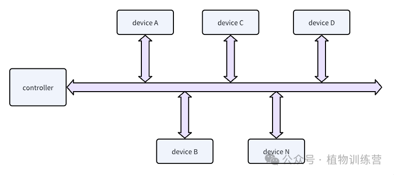
An I2C controller connects to multiple I2C slave devices; the I2C standard does not limit the number of devices that can be connected to a single bus, as long as the capacitive coupling and unique address requirements for each device are met. The connection access method is as described above.
If there is one device with a 7-bit address and another with a 10-bit address, the I2C specification states that the address range for 7-bit addresses is 0x08-0x77, with addresses below 0x08 being special or reserved addresses. Since 10-bit addresses are sent with a fixed bit pattern of 1111 0XX+(w/r), where xx represents the high 2 bits of the 10-bit address, followed by the lower 8 bits, the 10-bit address starts from 0x78. Therefore, to avoid conflicts between 10-bit and 7-bit addresses, the range for 7-bit addresses is limited to 0x77.
2 I2C Channel Expansion
If multiple identical devices need to be connected, to avoid violating the unique address requirement for each device, a multiplexer chip is added to isolate the addresses, requiring channel switching to access the corresponding device.
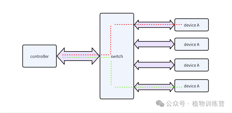
Access method: 1. Treat the switch as a slave device, first send a command to the switch chip, switch the channel, and then access the corresponding device A. It is important to control the entire access process with locks to avoid contention. 2. Use the existing mux driver in the Linux kernel to perform the switching action, allowing direct device access from user space.
3 Multiple Master Controllers on the I2C Bus
When there are multiple master controllers, access conflicts can be divided into two types: 1. Two controllers simultaneously access different or the same slave devices; 2. Two controllers simultaneously access each other.
To address master controller access conflicts, the following principles should be followed:
-
When accessing the bus, check if the bus is busy; if a start signal is received but no stop signal is received, or if the bus is not consistently high, it indicates that the bus is busy.
-
When two controllers simultaneously access different or the same devices, each controller will check every bit it sends; if a bit is sent as high but detected as low, that controller has lost arbitration and releases control.
-
After losing arbitration, the controller will switch to slave mode to avoid conflicts with the controller that successfully gained control.
-
If a controller acts as both a slave and a master, it must also have a unique slave address.
Extension:
Data transmitted over I2C must be 8 bits, but there is no requirement for the quantity of data transmitted; each 8 bits must be followed by an ACK bit. Data transmission starts from the MSB. If a device must complete other actions (such as interrupt handling) before it can continue receiving or sending the next byte, it can pull SCL low, causing the I2C controller to enter a wait state until it can receive or send the next byte, at which point SCL is released.
If the data line (SDA) is stuck LOW, the controller should send nine clock pulses. The device that held the bus LOW should release it sometime within those nine clocks.