Stay updated on the latest technology developments and applications, focusing on performance optimization and architectural design. We welcome your attention!
1. Network Layering
1. The relationship between the OSI seven layers and the TCP/IP four layers
- The OSI model introduces the concepts of services, interfaces, protocols, and layering, while TCP/IP adopts these concepts to establish the TCP/IP model.
- The OSI model has protocols and standards developed after the model itself, while TCP/IP developed protocols and applications first, then proposed a model based on the OSI model.
- The OSI model is a theoretical model, while TCP/IP is widely used and has become the de facto standard for network interconnection, encompassing various protocol families related to the Internet.
TCP: Transmission Control Protocol
UDP: User Datagram Protocol
|
OSI Seven-Layer Network Model |
TCP/IP Four-Layer Conceptual Model |
Corresponding Network Protocols |
|
Application Layer |
Application Layer |
HTTP, TFTP, FTP, NFS, WAIS, SMTP |
|
Presentation Layer |
Telnet, Rlogin, SNMP, Gopher |
|
|
Session Layer |
SMTP, DNS |
|
|
Transport Layer |
Transport Layer |
TCP, UDP |
|
Network Layer |
Network Layer |
IP, ICMP, ARP, RARP, AKP, UUCP |
|
Data Link Layer |
Data Link Layer |
FDDI, Ethernet, Arpanet, PDN, SLIP, PPP |
|
Physical Layer |
IEEE 802.1A, IEEE 802.2 to IEEE 802.11 |
2. What is a Protocol
Each layer is designed to perform a specific function. To achieve these functions, everyone must adhere to common rules. The rules that everyone follows are called “protocols”.
3. OSI Seven-Layer Protocol Model
(1) Application Layer – Application (Layer 7)
It is an application that communicates with other computers, corresponding to the communication services of application programs. For example, a word processing program without communication capabilities cannot execute communication code, and a programmer working on word processing does not care about OSI Layer 7. However, if a file transfer option is added, the word processor programmer will need to implement OSI Layer 7.
(2) Presentation Layer – Presentation (Layer 6)
This layer’s main function is to define data formats and encryption. For example, FTP allows you to choose to transfer in binary or ASCII format. If binary is chosen, the sender and receiver do not change the content of the file. If ASCII format is chosen, the sender converts the text from the sender’s character set to standard ASCII before sending the data. At the receiver’s end, standard ASCII is converted back to the receiver’s computer’s character set.
(3) Session Layer – Session (Layer 5)
This layer defines how to start, control, and end a session, including controlling and managing multiple bi-directional messages, so that when only part of a continuous message is completed, the application can be notified, allowing the data seen by the presentation layer to be continuous. In some cases, if the presentation layer receives all the data, it represents the data for the presentation layer.
(4) Transport Layer – Transport (Layer 4)
This layer’s functions include whether to choose error recovery protocols or non-error recovery protocols, multiplexing data streams for different applications on the same host, and reordering packets that are received out of order.
(5) Network Layer – Network (Layer 3)
This layer defines end-to-end packet transmission, identifying logical addresses that can identify all nodes, and defining how routing is implemented and learned. To accommodate transmission media with maximum transmission unit lengths less than packet lengths, the network layer also defines how to segment a packet into smaller packets.
(6) Data Link Layer – Data Link (Layer 2)
This layer defines how to transmit data over a single link. These protocols relate to various media being discussed.
(7) Physical Layer – Physical (Layer 1)
The physical layer specifications are standards concerning the characteristics of transmission media, which often reference standards set by other organizations. Connectors, frames, frame usage, current, encoding, and optical modulation are all part of various physical layer specifications. The physical layer often uses multiple specifications to define all details.
4. TCP/IP Four-Layer Model (Optimization of the OSI Seven-Layer Model)
The TCP/IP protocol system must be responsible for completing the following tasks:
- Breaking messages into manageable data blocks that can be effectively transmitted through the transmission medium.
- Connecting with network adapter hardware.
- Addressing, meaning the sending computer must be able to locate the receiving computer, and the receiving computer must be able to identify the data it is to receive.
- Routing data to the subnet where the destination computer is located, even if the source and destination subnets are on different physical networks.
- Executing error control, flow control, and acknowledgment; for reliable communication, the sending and receiving computers must be able to detect and correct transmission errors and control data flow.
- Receiving data from applications and transmitting it to the network.
- Receiving data from the network and transmitting it to applications.
To achieve the above functions, TCP/IP developers used a modular design, thus establishing a protocol model.
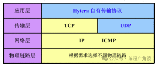
Hierarchical structuring of TCP/IP is beneficial. For example, if the Internet were governed by a single protocol, any design change would require replacing all parts. However, with layering, only the affected layer needs to be replaced. Once the interfaces between layers are well-defined, the internal design of each layer can be modified freely.
It is worth mentioning that after layering, the design also becomes relatively simpler. Applications at the application layer can focus solely on the tasks assigned to them without needing to understand where the other party is located on Earth, what their transmission route is, or whether delivery can be ensured.
(1) Host to Network Layer/Physical Link Layer
This layer is responsible for sending raw data packets over lower-level networks such as Ethernet and WiFi, operating at the network interface card level, using MAC addresses to identify devices on the network, hence it is also called the MAC layer..
In fact, the TCP/IP reference model does not truly describe the implementation of this layer; it only requires that an access interface be provided to the upper layer – the network layer, to transmit IP packets. Since this layer is not defined, its specific implementation methods will vary with different network types.
This layer handles the hardware part of connecting to the network, including operating system control, hardware device drivers, NIC (Network Interface Card), and physical visible components such as fiber optics (including connectors and all transmission media). All hardware aspects fall within the scope of the link layer.
(2) Network Layer
The network interconnection layer is the core of the entire TCP/IP protocol stack, responsible for sending packets (data packets) to the target network or host (establishing “host-to-host” communication). The network layer handles the data packets flowing over the network. A data packet is the smallest unit of data for network transmission. This layer specifies the path (the so-called transmission route) to reach the other computer and transmits the data packet to the other party.
Using IP addresses instead of MAC addresses, it connects many local area networks and wide area networks into a virtual large network, where finding devices only requires “translating” the IP address back into a MAC address.
At the same time, to send packets quickly, it may be necessary to transmit packets along different paths simultaneously. Therefore, the order in which packets arrive may differ from the order in which they were sent, requiring the upper layer to sort the packets. The role of the network layer is to select a transmission route among many options. The network interconnection layer defines packet formats and protocols, namely the IP protocol (Internet Protocol).
In addition to routing functions, the network interconnection layer can also interconnect different types of networks (heterogeneous networks). Furthermore, the network interconnection layer must also perform congestion control functions.
(3) Transport Layer
In the TCP/IP model, the transport layer’s function is to enable peer entities on the source and destination hosts to conduct sessions/data transmission (establishing “port-to-port” communication). The transport layer defines two protocols with different qualities of service: Transmission Control Protocol (TCP) and User Datagram Protocol (UDP).
TCP is a connection-oriented, reliable protocol. It reliably sends the byte stream from one host to other hosts on the Internet. At the sender’s end, it is responsible for dividing the byte stream received from the upper layer into segments and passing them to the lower layer. At the receiver’s end, it is responsible for reassembling the received segments and delivering them to the upper layer. The TCP protocol also handles end-to-end flow control to prevent a slow-receiving party from lacking sufficient buffer space to receive a large amount of data sent by the sender.
UDP is an unreliable, connectionless protocol, mainly suitable for situations where message ordering and flow control are not required.
(4) Application Layer
The application layer determines the communication activities when providing application services to users. The TCP/IP model combines the functions of the session layer and presentation layer from the OSI reference model into the application layer.
The application layer introduces different application layer protocols for different network applications. Some are based on TCP, such as File Transfer Protocol (FTP), Telnet, and Hypertext Transfer Protocol (HTTP), while others are based on UDP.
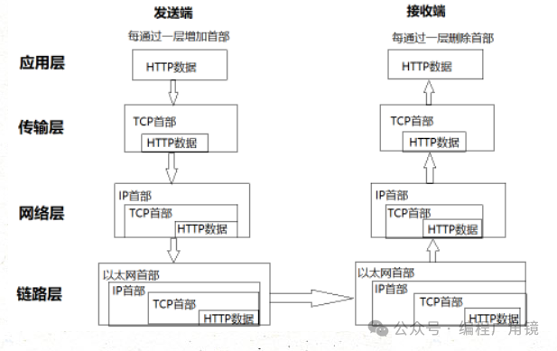
5. TCP/IP Communication Transmission Flow
First, as the sending client, an HTTP request is issued at the application layer (HTTP protocol) to view a specific web page.
Next, for transmission convenience, at the transport layer (TCP protocol), the data received from the application layer (HTTP request message) is segmented, and each message is tagged with sequence numbers and port numbers before being forwarded to the network layer.
At the network layer (IP protocol), the MAC address as the communication destination is added before forwarding to the link layer. Thus, the communication request sent to the network is fully prepared.
The receiving server receives the data at the link layer and sends it sequentially to the upper layers until it reaches the application layer. Only when it reaches the application layer can it be considered that the HTTP request sent by the client has been truly received.
2. TCP/IP Packet Format
1. IP Packet Format
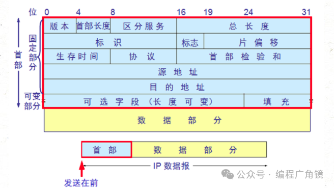
The IP protocol is the core protocol in the TCP/IP protocol family. It provides unreliable, connectionless services, relying on other layer protocols for error control. In a local area network environment, the IP protocol is often encapsulated in Ethernet frames for transmission. All TCP, UDP, ICMP, and IGMP data are encapsulated in IP datagrams for transmission.
-
Version field: 4 bits. Indicates the version number of the IP protocol implementation, currently generally IPv4, which is 0100.
-
Header Length: The length of the IP header. The sum of the fixed part length (20 bytes) and the variable part length. Occupies 4 bits. The maximum is 1111, which is decimal 15, indicating that the maximum length of the IP header can be 15 * 32 bits (4 bytes), which is a maximum of 60 bytes. Excluding the fixed part length of 20 bytes, the maximum length of the variable part is 40 bytes.
-
Type of Service (TOS) field: 8 bits. The first 3 bits are the precedence subfield (now ignored). The 8th bit is reserved. The 4th to 7th bits represent delay, throughput, reliability, and cost. When they are set to 1, they represent the minimum delay, maximum throughput, highest reliability, and minimum cost, respectively. Only one of these 4 bits can be set to 1. They can all be 0, which indicates general service. The type of service field declares how the datagram can be processed when transmitted by the network system. For example, the TELNET protocol may require minimal delay, the FTP protocol (data) may require maximum throughput, the SNMP protocol may require highest reliability, and the NNTP (Network News Transfer Protocol) may require minimum cost, while the ICMP protocol may have no special requirements (all 4 bits are 0). In practice, most hosts ignore this field, but some dynamic routing protocols like OSPF (Open Shortest Path First Protocol) and IS-IS (Intermediate System to Intermediate System Protocol) can make routing decisions based on the values of these fields.
-
Total Length field: 16 bits. Indicates the total length of the entire datagram (in bytes). The maximum length is 65535 bytes.
-
Identification: 16 bits. Used to uniquely identify each datagram sent by the host. Typically, the value increments by 1 for each sent message.
-
Flags field: 3 bits. Indicates whether a datagram requires fragmentation.
-
Fragment Offset field: 13 bits. If a datagram requires fragmentation, this field indicates the offset of the fragment from the beginning of the original datagram.
-
Time to Live (TTL) field: 8 bits. Used to set the maximum number of routers a datagram can pass through. Set by the source host sending the data, typically 32, 64, 128, etc. Each time it passes through a router, its value decreases by 1, and when it reaches 0, the datagram is discarded.
-
Protocol field: 8 bits. Indicates the type of upper layer protocol encapsulated by the IP layer, such as ICMP (1), IGMP (2), TCP (6), UDP (17), etc.
-
Header Checksum field: 16 bits. The content is the checksum calculated based on the IP header. The calculation method is: sum the binary complements of each 16 bits in the header. (Unlike ICMP, IGMP, TCP, and UDP, IP does not check the data following the header).
-
Source IP Address, Destination IP Address fields: each occupies 32 bits. Used to indicate the source host address of the IP datagram and the destination host address of the received IP datagram.
-
Options field: 32 bits. Used to define some optional items: such as recording paths, timestamps, etc. These options are rarely used, and not all hosts and routers support these options. The length of the options field must be a multiple of 32 bits; if not, it must be padded with 0 to meet this length requirement.
2. TCP Segment Format
TCP is a reliable, connection-oriented byte stream service. The source host must first establish a connection with the destination host before transmitting data. Then, on this connection, the numbered segments are sent and received in order. At the same time, each segment must be acknowledged to ensure reliability. If the destination host does not acknowledge the sent segment within a specified time, the source host will resend that segment.
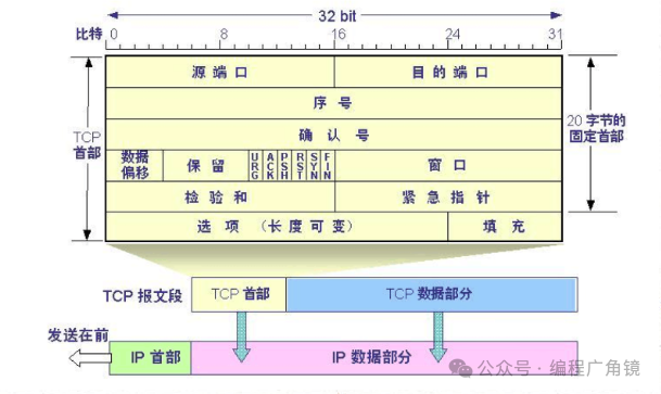
● Source, Destination Port Number fields: 16 bits. The TCP protocol identifies the source and destination application processes using “ports”. Port numbers can be any number between 0 and 65535. When a service request is received, the operating system dynamically assigns a port number to the client’s application. On the server side, each service provides services to users at “well-known ports”.
● Sequence Number field: 32 bits. Used to identify the byte stream sent from the TCP source to the TCP destination, indicating the first data byte in this segment.
● Acknowledgment Number field: 32 bits. The acknowledgment number field is only valid when the ACK flag is set to 1. It contains the next data byte that the destination expects to receive from the source.
● Header Length field: 4 bits. Indicates the number of 32 bits occupied by the header. The TCP header length without any option fields is 20 bytes; the maximum TCP header length can be 60 bytes.
● Flags field (U, A, P, R, S, F): 6 bits. The meanings of each bit are as follows:
◆ URG: Urgent pointer is valid.
◆ ACK: Acknowledgment number is valid.
◆ PSH: The receiver should pass this segment to the application layer as soon as possible.
◆ RST: Rebuild the connection.
◆ SYN: Initiate a connection.
◆ FIN: Release a connection.
● Window Size field: 16 bits. This field is used for flow control. The unit is the number of bytes, and this value is the number of bytes the local machine expects to receive at once.
● TCP Checksum field: 16 bits. The checksum is calculated for the entire TCP segment, including the TCP header and TCP data, and is verified by the destination.
● Urgent Pointer field: 16 bits. It is an offset that, when added to the value in the sequence number field, indicates the sequence number of the last byte of urgent data.
● Options field: 32 bits. May include options such as “Window Scale Factor”, “Timestamps”, etc.
3. UDP Segment Format
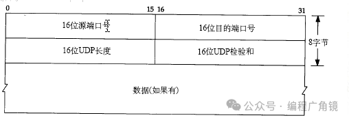
UDP is an unreliable, connectionless datagram service. The source host does not need to establish a connection with the destination host before transmitting data. The data is sent directly to the destination host after being tagged with source and destination port numbers and other UDP header fields. In this case, the reliability of each segment depends on the upper layer protocol. In situations where data transmission is small and infrequent, UDP is more efficient than TCP.
-
Source, Destination Port Number fields: 16 bits. The function is the same as the port number fields in the TCP segment, used to identify the source and destination application processes.
-
Length field: 16 bits. Indicates the total length in bytes of the UDP header and UDP data.
-
Checksum field: 16 bits. Used to check the UDP header and UDP data. Unlike TCP, this field is optional for UDP, while the checksum field in TCP segments is mandatory.
4. Socket
Each TCP and UDP segment contains source and destination port fields. Sometimes, we refer to an IP address and a port number collectively as a socket, and a socket pair can uniquely identify both sides of each TCP connection in an interconnected network (client IP address, client port number, server IP address, server port number).
It is important to note that different application layer protocols may be based on different transport layer protocols, such as FTP, TELNET, and SMTP protocols based on reliable TCP, while TFTP, SNMP, and RIP are based on unreliable UDP.
Additionally, some application layer protocols occupy two different port numbers, such as FTP’s ports 20 and 21, and SNMP’s ports 161 and 162. These application layer protocols provide different functions on different ports. For example, FTP’s port 21 is used to listen for user connection requests, while port 20 is used to transfer user file data. Similarly, SNMP’s port 161 is used for SNMP management processes to retrieve data from SNMP agents, while port 162 is used for SNMP agents to actively send data to SNMP management processes.
Some protocols use services provided by different transport layer protocols. For example, the DNS protocol uses both TCP port 53 and UDP port 53. The DNS protocol provides domain name resolution services on UDP port 53 and DNS zone file transfer services on TCP port 53.