First, we need to know what UART is?
UART (Universal Asynchronous Receiver/Transmitter) is a common asynchronous serial communication interface that is widely used in electronic circuits. The UART interface function circuit is generally integrated within the chip, and it can be used directly if the selected microcontroller chip has this function.
The mystery of the UART communication protocol, in short, is to transmit data in binary form bit by bit. During this process, a high level on the signal line represents ‘1’, while a low level represents ‘0’. When two devices communicate via the UART serial port, they must first reach a consensus on the transmission rate and data bit settings. This is like two friends agreeing on the speed and topic of conversation before chatting, ensuring that the information can be accurately conveyed.
UART Hardware Connection Method
The hardware connection is quite simple, requiring only three lines, using cross-connected transmission and reception. Note that when designing the specific circuit, if the voltage levels of the two devices are inconsistent, level conversion must be performed before connecting to prevent leakage or cross-voltage. As shown in the figure below:
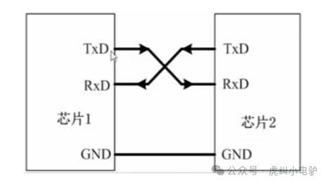
TX: Transmit data end, must connect to the RX of the opposite device
RX: Receive data end, must connect to the TX of the opposite device
GND: Ensures both devices share a common ground, providing a unified reference plane
Understanding UART Interface Protocol
As a type of asynchronous serial communication protocol, UART works by transmitting data bytes one bit at a time. The protocol is as follows:
|
Format |
Start Bit |
Data |
Parity |
Stop Bit |
|
Length |
1 |
5-9 |
0-1 |
1-2 |
Idle Bit: The UART protocol specifies that when the bus is idle, the state of the signal line is 1, which is a high level.
Start Bit: When starting data transmission, the sender must first send a low level 0 to indicate the beginning of the character transmission. This is because the idle bit is always high, so when starting the first communication, a signal that is distinctly different from the idle state, which is low, is sent.
Data Bit: After the start bit, the data to be transmitted follows, which can be 5, 6, 7, 8, or 9 bits, forming a character, usually 8 bits. The least significant bit is sent first, followed by the most significant bit.
Parity Bit: After the data bits are transmitted, a parity check is performed. The parity bit is actually an adjustment count, and serial port checks can be done in several ways::
① No Parity (no parity);② Odd Parity (odd parity): If the number of ‘1’s in the data bits is even, the parity bit is 1; if the number of ‘1’s is odd, the parity bit is 0.; ③ Even Parity (even parity): If the number of ‘1’s in the data is even, the parity bit is ‘0’; if odd, the parity bit is ‘1’.;
Stop Bit: The end of data transmission can be indicated by 1, 1.5, or 2 bits of high level. Baud Rate: The data transmission rate is expressed in baud rate, with the unit bps. Common baud rates include 9600bps, 115200bps, etc.
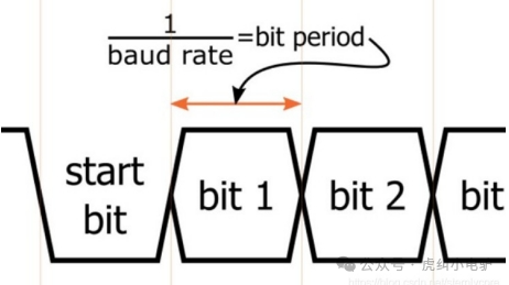
For example, if the serial port baud rate is set to 9600bps, then the time required to transmit one bit is 1/9600≈104.2us.
The above is a collection and sharing of knowledge about the UART interface. Everyone is welcome to provide guidance and discussion.