


Three Core Modes of PLC Control for Servo Motors:
A Deep Dive from Principles to Examples

Industrial Control Expert Yang Focuses on PLC Teaching for 17 Years
In the field of automation control, the collaborative control of PLC and servo motors is a key technology for achieving precise motion control. Today, we will systematically analyze the three classic modes of PLC control for servo motors, combined with examples from the SINAMICS V90 system, to present a technical sharing that combines theoretical depth with engineering practicality.
01
Torque Control: The Art of Precise Force Regulation
The torque control mode directly sets the output torque of the motor shaft through external analog input or address assignment. For example, with a proportional relationship of 10V corresponding to 5Nm, when an input of 5V is provided, the motor shaft will output a torque of 2.5Nm. Its dynamic characteristics are as follows:
-
When load < 2.5Nm, the motor rotates forward
-
When load = 2.5Nm, the motor remains stationary
-
When load > 2.5Nm, the motor rotates in reverse (common in gravity load scenarios)
This mode supports two control methods: real-time adjustment of analog quantities and modification of communication address parameters, making it particularly suitable for industrial scenarios requiring dynamic force control, such as tension control and torque loading.
02
Position Control: The Ultimate Pursuit of Positioning Accuracy
The position control mode uses pulse input as the core control signal:
-
Pulse frequency determines the rotation speed
-
Pulse count precisely controls the rotation angleSome high-end servo systems also support direct assignment of speed and displacement parameters via communication methods. By simultaneously implementing dual closed-loop control of speed and position, this mode is widely used in high-precision positioning scenarios such as CNC machine tools and automatic assembly equipment, making it the “coordinate commander” of automated production lines.
03
Speed Mode: An Optimized Solution for Dynamic Response
Speed control can be achieved through either analog input or pulse frequency. In systems with upper-level PID control, this mode can also achieve positioning functions, but it requires real-time feedback of the motor or load position signal to the main control system. Typical application scenarios include:
-
Conveyor line speed synchronization control
-
Variable frequency adjustment of fan and pump loads
-
Speed coordination of multi-axis linkage systems
04
Technical Example:
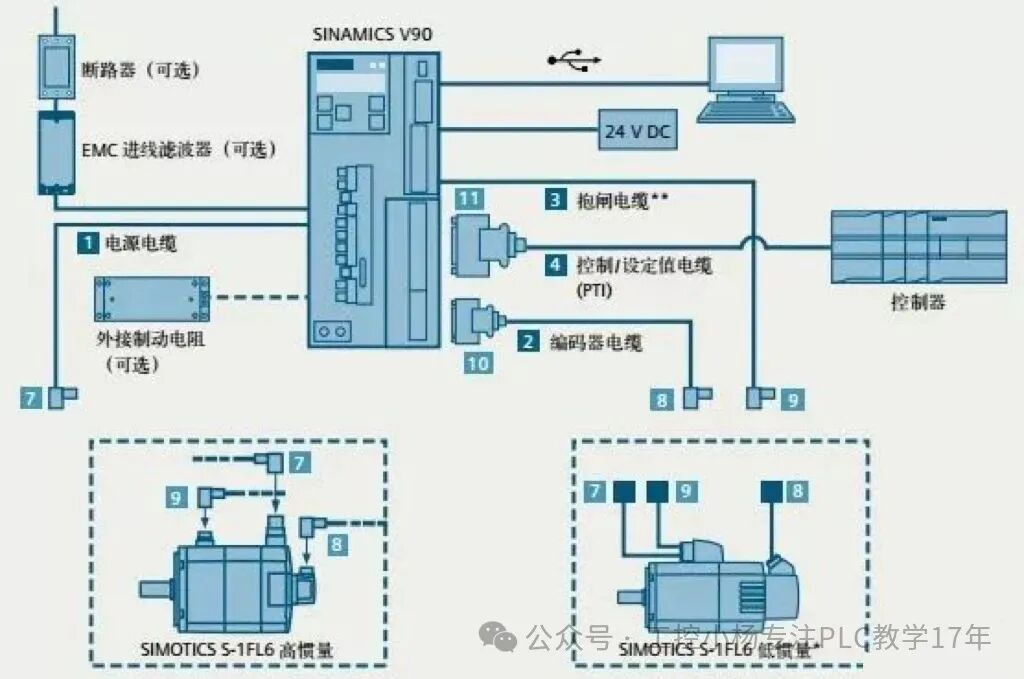
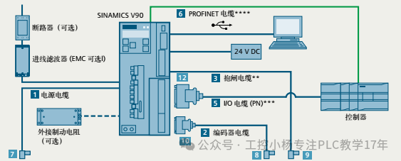
Engineering Implementation of the SINAMICS V90 System
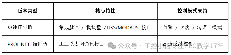
The Siemens SINAMICS V90 servo system is divided into two major versions based on different application needs.
Key Points of Hardware Wiring:
1. Power System: All PTO signals must share the same 24V power supply to ensure signal integrity
2. Digital Input: Supports both NPN/PNP types, compatible with different controller interfaces
3. Brake Control:
-
200V drive requires external relay connection for the brake circuit
-
400V drive can be controlled directly via I/O cable
4. Signal Isolation: It is recommended to isolate the power supply for digital input/output from the controller to enhance anti-interference capability.
The collaborative control of PLC and servo motors is like the “nervous system” and “executive limbs” in the field of industrial automation. From the force sensing grasp of torque control to the precise positioning of position control, and to the dynamic response optimization of speed mode, these three control modes form a complete technical system for industrial motion control. Through engineering practices with advanced servo systems like SINAMICS V90, we gain insight into how automation technology transforms digital commands into precise mechanical actions.
[END]