The Raspberry Pi Pico small MCU module, with its low price, rich features, and easy development, provides a convenient platform for many students from non-electronic majors to design creative project prototypes. The following experiments are some basic demonstration experiments made for CDIE course design students.
▌01 PI Pico Experiment Board
In Basic Testing of RASPBERRY PI PICO Development Board[1], the basic setup of the PI Pico development board is provided. By installing the Thonny development environment[2], it is easy to perform preliminary development on the Pi Pico.
Below, based on the examples given in Raspberry Pi Pico Python SDK[3], some basic modules of the PI Pico will be tested.
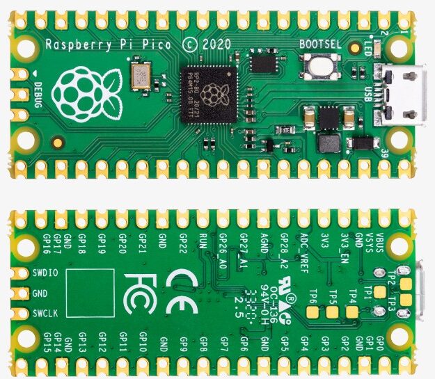
For the pin configuration of the Pi Pico, please refer to the Pi Pico Data Sheet[4] for the pin diagram definition:
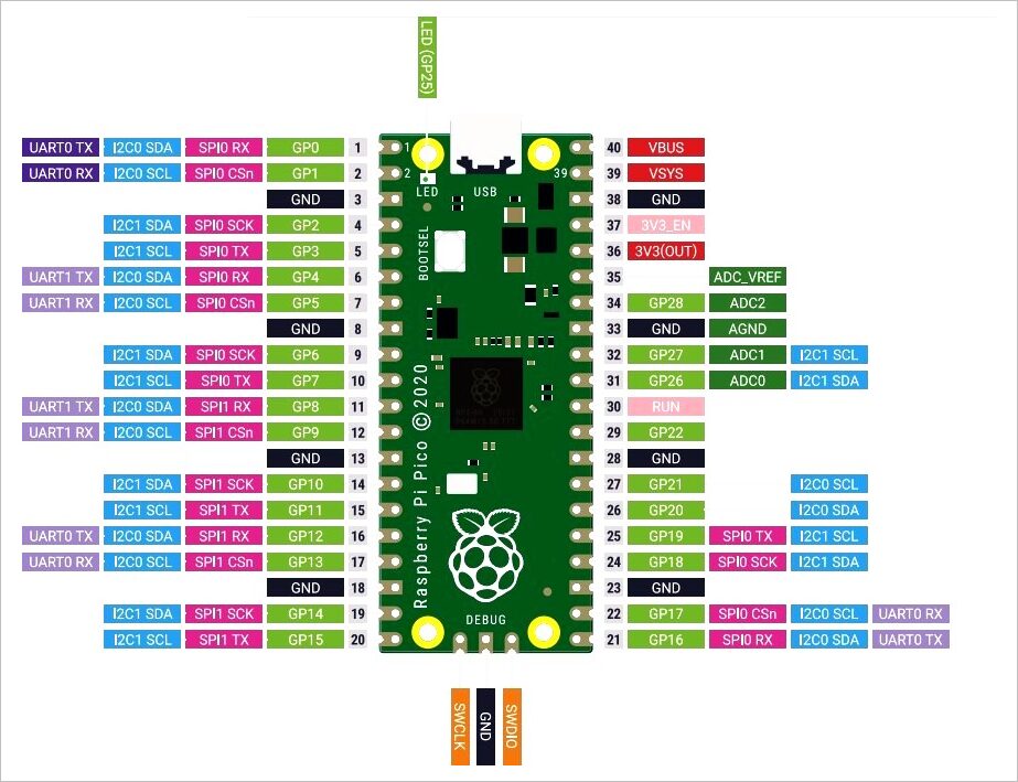
More information about Pi Pico can be obtained from the Pi Pico Official Website[5].
▌02 Basic Testing
1. Flash LED on Board
from machine                import Pin,Timer
from time                   import sleep_us

led = Pin(25, Pin.OUT)
tim = Timer()

print("Flash LED.")

def tick(timer):
    global led
    led.toggle()

tim.init(freq=2, mode=Timer.PERIODIC, callback=tick)

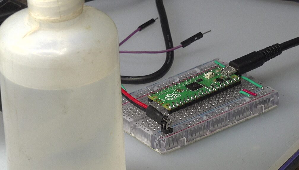
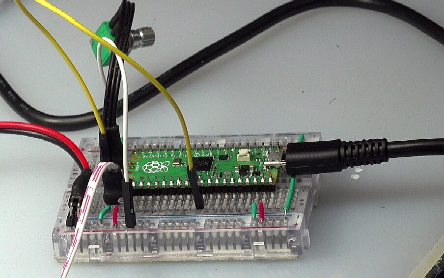
▲ Experimental Circuit Board
2. UART
(1) Test Program
from machine                import UART,Pin,Timer
from time                   import sleep_us

uart = UART(0, baudrate=115200, tx=Pin(0), rx=Pin(1), bits=8, parity=None, stop=1)
led = Pin(25, Pin.OUT)

tim = Timer()

print("Send UART.")

def tick(timer):
    global uart, led

    led.toggle()
    uart.write(b'\x55')

tim.init(freq=10, mode=Timer.PERIODIC, callback=tick)
3. ADC
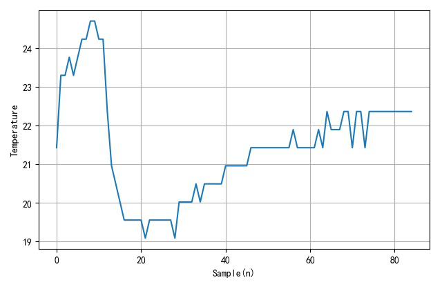
Read the internal temperature of the chip through ADC channel 4. During this process, use your hand to touch the surface of the Pi Pico to heat it, or use alcohol to spray the surface of the chip to cool it.
import machine
import utime

sensor_temp = machine.ADC(4)
conversion_factor = 3.3/(65535)

while True:
    read = sensor_temp.read_u16() * conversion_factor

    temperature = 27 - (read - 0.706) / 0.001721
    print(temperature)
    utime.sleep(2)
4. PWM
(1) PWM Driving LED
Control the waveform of the onboard LED using PWM.
from machine                import Pin,PWM
import time

pwm = PWM(Pin(25))

pwm.freq(1000)

duty = 0
direction = 1

for _ in range(16*255):
    duty += direction

    if duty > 255:
        duty = 255
        direction = -1
    elif duty < 0:
        duty = 0
        direction = 1

    pwm.duty_u16(duty*duty)
    time.sleep(0.001)
PWM is software PWM, which can be set on any pin. Preliminary tests have been performed on Pin0, 15, 16, etc., all showing similar waveforms.
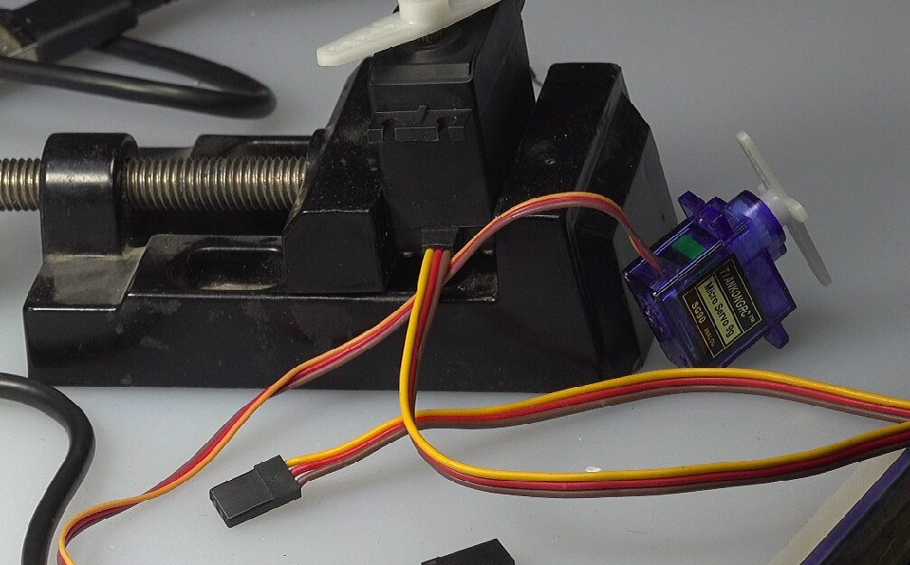
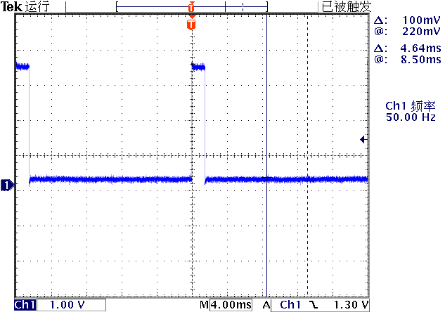
(2) PWM Driving Servo
The servo uses a frequency of 50Hz, with pulse widths of 1.0 ~ 2.0ms as control signals. Below is the output control pulse generated when the servo position is in the middle.
from machine                import Pin,PWM
import time

pwm = PWM(Pin(15))

pwm.freq(50)
pwm.duty_u16(4915)
The servo has three wires:
-
Brown: GND -
Red: +4.5 ~ +6V -
Yellow: Command Pulse Signal
The formula for calculating Duty_16 is:
The relationship between pulse width and duty_u16:
| Pulse Width (ms) | duty u16 |
|---|---|
| 1 | 3277 |
| 1.5 | 4915 |
| 2 | 6554 |
from machine                import Pin,PWM
import time

pwm = PWM(Pin(16))

pwm.freq(50)

for _ in range(100):
    pwm.duty_u16(3276)
    print("Out pulse width : 1ms")
    time.sleep(1)

    print("Out pulse width : 2ms.")
    pwm.duty_u16(6553)
    time.sleep(1)
(3) PWM + ADC Experiment
Using a potentiometer to change the voltage input to ADC(0), the microcontroller obtains the corresponding ADC value, changing the PWM output so that its output time width varies proportionally from 1ms to 2ms.
You can see the output angle of the servo changes with the potentiometer.
from machine                import Pin,PWM
import time

pwm = PWM(Pin(16))

pwm.freq(50)

control = machine.ADC(0)

for _ in range(1000):
    adc = control.read_u16()
    duty = int(adc * (6553-3276)/0xffff) + 3276
    pwm.duty_u16(duty)
    time.sleep(0.1)
5. Interrupt IRQ
Use the falling edge of pin PIN2 to generate an interrupt. The example program is as follows:
from machine                import Pin

p2 = Pin(2, Pin.IN, Pin.PULL_UP)

p2.irq(lambda pin:print("IRQ with flag:",
        pin.irq().flags()),
        Pin.IRQ_FALLING)
Using a jumper to ground PIN2. Each time it is connected, an interrupt will be triggered.
▌Conclusion
Through several basic Pi Pico experiments, preliminary application examples of this module are provided.
References
Basic Testing of RASPBERRY PI PICO Development Board: https://zhuoqing.blog.csdn.net/article/details/114037888
[2]Installing Thonny Development Environment: https://zhuoqing.blog.csdn.net/article/details/114064833
[3]Raspberry Pi Pico Python SDK: https://datasheets.raspberrypi.org/pico/raspberry-pi-pico-python-sdk.pdf
[4]Pi Pico Data Sheet: https://datasheets.raspberrypi.org/pico/pico-datasheet.pdf
[5]Pi Pico Official Website: https://www.raspberrypi.org/documentation/rp2040/getting-started/
Warm Reminder
Due to recent changes in WeChat public account push rules, if you want to frequently see our articles, you can click “Like” or “View” at the bottom of the page after reading each time, so that the articles pushed each time will appear in your subscription list in a timely manner.