“The clock frequency is the core of the microcontroller, affecting peripheral communication, timing, and other functions. Simulation tools can observe its frequency in real-time, aiding in configuration verification and troubleshooting. This article introduces four simple and convenient methods for testing clock frequencies in the Keil-MDK environment, using the STM32F407 as an example to illustrate the operations and results.”“

Introduction
The clock frequency is the “basal metabolic rate” of the microcontroller system, and its accuracy directly affects core functions such as peripheral communication, timing precision, power consumption control, and system scheduling. Simulation tools, through real-time, non-invasive (no hardware circuit damage) observation capabilities, help developers quickly verify clock configurations, locate software and hardware issues, and optimize system performance, serving as a key assurance tool in microcontroller development from “function implementation” to “stable and reliable”.
Below are several methods for testing clock frequencies in the Keil-MDK simulation environment, which are very simple and convenient to use.
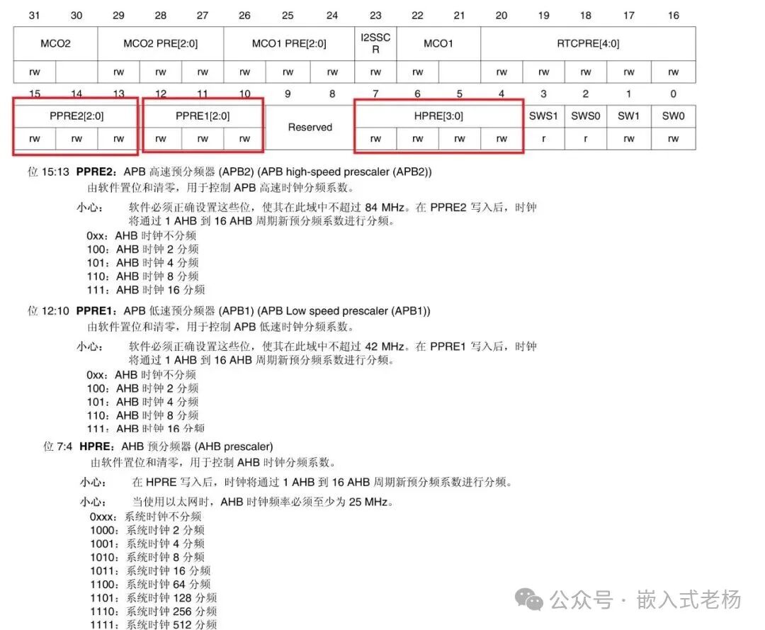
The following program configures SYSCLK to 168MHz, with APB1, APB2, and AHB clocks derived from SYSCLK (set through the PPRE1, PPRE2, and HPRE fields of RCC_CFGR). Below is a detailed explanation of the RCC_CFGR register fields.The base address of RCC is: 0x40023800;The offset address of the RCC_CFGR register is: 0x08;
Method One
Using the System Viewer Tool
1. Go to Debug → Click Peripherals → RCC.
2. In the RCC window, observe the following register bits in real-time:
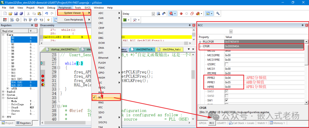
The above image shows the actual simulation results.
The PPRE1 field of RCC->CFGR is the APB1 prescaler value, 0x05 indicates a division by 4, so the APB1 clock frequency is 168MHz/4=42MHz;
The PPRE2 field of RCC->CFGR is the APB2 prescaler value, 0x04 indicates a division by 2, so the APB2 clock frequency is 168MHz/2=84MHz;
The HPRE field of RCC->CFGR is the AHB prescaler value, 0x00 indicates a division by 1, so the AHB clock frequency is 168MHz/1=168MHz;
Method Two
Directly reading registers in the Memory window
1. In the Memory1 address bar, enter:
0x40023800, which is the base address of RCC.
2. Observe the offset:
The offset address of the RCC->CFGR register is 0x08, which means the RCC->CFGR address is 8 addresses to the right of the RCC base address.
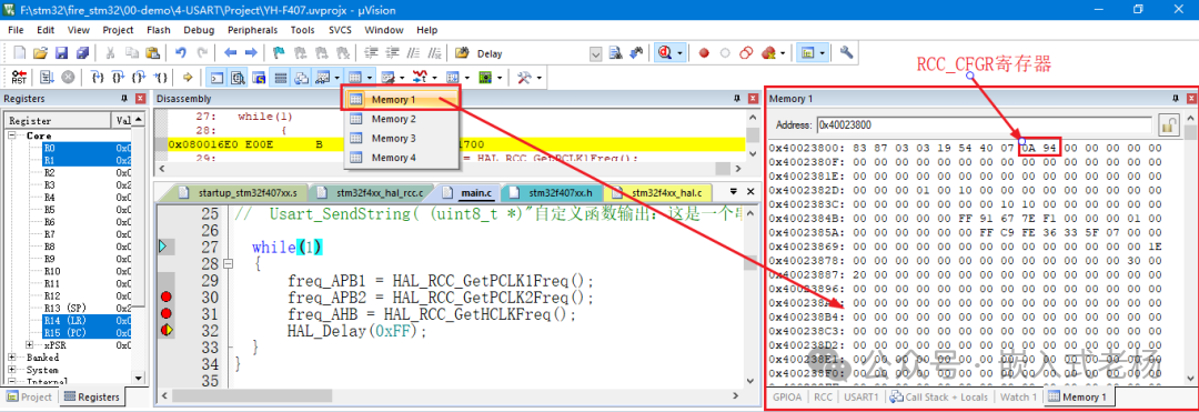
The value read from the RCC->CFGR address in the above image is 0x940A (STM32F4xx is in little-endian mode), and the detailed field analysis of the register is the same as in Method One.
Method Three
Calling HAL library functions and observing with Watch
1. Add the following code in the main function
freq_APB1 = HAL_RCC_GetPCLK1Freq();freq_APB2 = HAL_RCC_GetPCLK2Freq(); freq_AHB = HAL_RCC_GetHCLKFreq();HAL_RCC_GetPCLK1Freq(): reads the APB1 frequency value;
HAL_RCC_GetPCLK2Freq(): reads the APB2 frequency value;
HAL_RCC_GetHCLKFreq(): reads the AHB frequency value;
The unit is Hz.
2. Use the Watch tool to observe the results
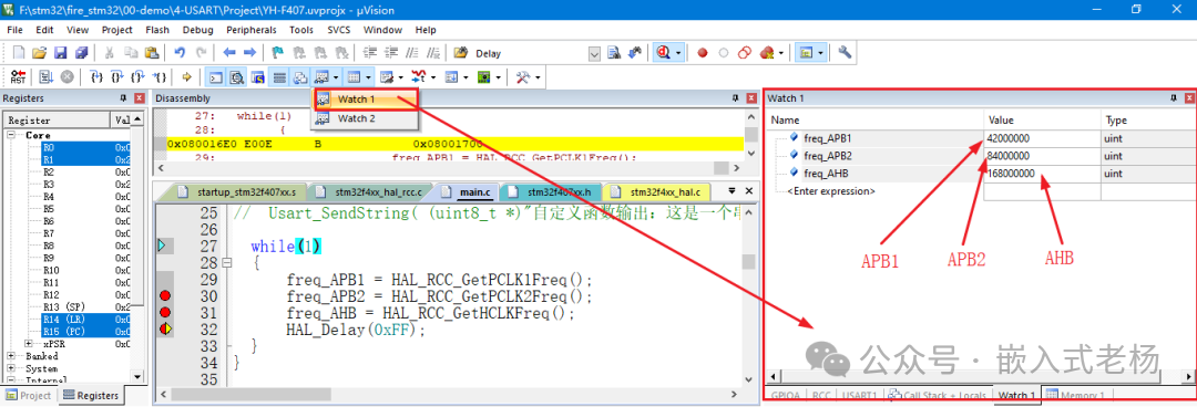
The observed results are:
APB1 clock frequency is 42MHz;
APB2 clock frequency is 84MHz;
AHB clock frequency is 168MHz.
Method Four
Accessing register addresses and observing with Watch
1. In the Watch window, enter the following expressions:
(*((volatile uint32_t *)0x40023808) & (0x7 << 13))>>13 // Read the PPRE2 field of the RCC_CFGR register
(*((volatile uint32_t *)0x40023808) & (0x7 << 10))>>10 // Read the PPRE1 field of the RCC_CFGR register
(*((volatile uint32_t *)0x40023808) & (0x7 << 4))>>4 // Read the HPRE field of the RCC_CFGR register
2. Use the Watch tool to observe the results
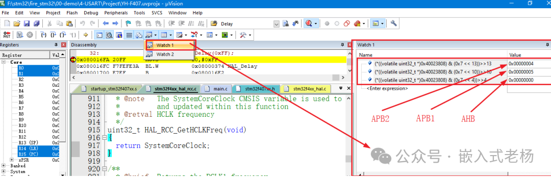
The observed results are:
The PPRE2 field of the RCC_CFGR register, 0x4 indicates a division by 2, so the APB2 clock frequency is 168MHz/2=84MHz;
The PPRE1 field of the RCC_CFGR register, 0x5 indicates a division by 4, so the APB1 clock frequency is 168MHz/4=42MHz;
The HPRE field of the RCC_CFGR register, 0x0 indicates a division by 1, so the AHB clock frequency is 168MHz/1=168MHz.
The software and hardware used in this article are described as follows:
1. Microcontroller model: STM32F407ZGT6 (25MHz external crystal);
2. Software development environment: Keil MDK v5.36;
3. Pack version: STM32F4xx_DFP v3.0.0;
4. Compiler: ARM Compiler v5;
5. STM32 project version: Standard HAL library or register version;
6. Downloader: JLINK downloader, SWD interface;
7. The software and hardware case in this article is for personal learning only and must not be used for commercial purposes.
References for this article:
“STM32F4xx Chinese Reference Manual (RM0090)”;
“STM32F405xx STM32F407xx Datasheet (DS8626)”.