




Technical Article: Resistance and Resistivity of PCB Substrates

Ningbo Turbulence Laboratory
01
Insulation Resistance, Volume Resistivity, and Surface Resistivity
In engineering, materials are roughly classified into four categories based on conductivity, with PCB substrates being a typical insulating material. Insulation resistance is the resistance value exhibited by insulating materials under direct current (DC) voltage, which is the most basic and straightforward indicator for assessing the quality of insulation materials. The fundamental requirement for PCB substrate materials is insulation, and the insulating performance of the substrate is usually expressed in terms of surface resistivity and volume resistivity.
Table 1: Conductivity and Resistivity of Insulators, Semiconductors, Conductors, and Superconductors.
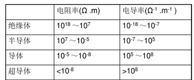
Source: “Polymer Physics (3rd Edition)” by He Manjun et al., Fudan University Press, pages 268-289.
Surface Resistivity refers to the resistance along the surface of the substrate, describing the resistance between two conductors. Surface insulation resistivity is defined as the ratio of the DC voltage applied between any two points on the surface of an insulating material to the total current flowing between those two points, generally expressed in ohms (Ω).
Volume Resistivity refers to the resistance between two layers of conductors along the Z-axis of the laminate material. Volume resistivity is defined as the ratio of the DC voltage applied across the electrodes embedded in the substrate to the current flowing through the electrodes, generally expressed in Ω·cm.
The volume resistivity and surface resistivity of a sample are understood from a measurement perspective. In reality, the surface resistivity and volume resistivity of materials are inherent properties of the materials. Volume resistivity is closely related to factors such as material composition and structure; surface resistivity is mainly influenced by the chemical characteristics of the material’s surface, cleanliness, morphological structure, and surrounding environment (primarily humidity). The essence of both reflects the insulation characteristics of the material.
Since resistivity is the DC resistivity tested under direct current, this property has greater reference value for DC applications. Generally, in high-frequency applications, we are more concerned with the dielectric properties of substrate materials rather than resistivity (conductivity).
02
The Significance of Resistivity for Substrates
The significance of resistivity values for substrates can be understood from the following aspects::
A high resistivity means that it is difficult for current to flow through the interior or surface of the substrate, preventing leakage between layers (volume resistivity) or between wires (surface resistivity), ensuring circuit isolation. This is particularly important for multilayer PCBs, high-voltage applications (such as power modules), and high-density interconnects (HDI).
Generally, when selecting materials for PCB applications, materials with high volume resistivity can often withstand higher electric field strengths, reducing the risk of dielectric breakdown and enhancing the reliability of devices in relatively high-voltage scenarios (such as power electronics). However, it should be noted that the above statement is not physically rigorous— the dielectric breakdown performance of polymers and resistivity (conductivity) are two completely different concepts. Under high electric field conditions, the current-voltage relationship generally does not conform to Ohm’s law. High resistivity materials do not necessarily imply high breakdown field strength. Therefore, actual sample confirmation is required.
In resistivity testing, we need to introduce humidity conditions for testing: Samples are treated at 90% relative humidity and 35°C for 96 hours (96/35/90). In humid environments, water adsorbed on the surface may form conductive pathways; thus, the polarity and porosity of the polymer itself can affect the test results of surface resistivity. For example, phenolic resin substrates exhibit conductivity thousands of times higher at 90% relative humidity than under dry conditions. The influence of humidity on the resistance values of substrate materials is detrimental for special environmental applications, such as aerospace and marine, and measures need to be taken to avoid this.
03
Testing of Volume Resistivity and Surface Resistivity
Our testing follows the PC-TM-650 method 2.5.17.1, as well as the national standard GB/T4722-2017 8.3. The sample size is 101.6mm × 101.6mm, and the laminate thickness is greater than 0.51mm. The equipment used is a high-resistance meter (for example, Keysight’s B2985B). Samples are prepared using standard imaging and etching processes according to method 2.5.17.
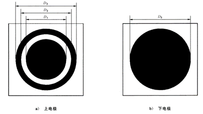
Figure 1: Test pattern for substrate resistivity (double-sided copper-clad substrate, the black area is the conductor layer)
All measurements are conducted under 500V DC, with the voltage applied to the sample for 60 seconds. Before the resistance reading, ensure the test structure is stable. The electrode structure is a consistent three-electrode system, as shown in Figure 2, although the circuit connection of the electrodes varies depending on the content being tested.
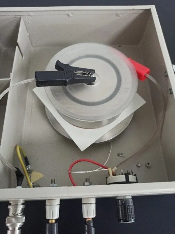
Figure 2: Three-electrode system
For the testing of volume resistivity, the electrode connection is as shown in Figure 3 (A): the ring electrode 3 and the measuring electrode 2 are at the same potential, so there is no current flowing through the gap between the two electrodes. Since the current between the bottom electrode 1 and the ring electrode 3 does not flow through ammeter A, the current on ammeter A only represents the volume current I between the bottom electrode 1 and the measuring electrode 2. Thus, U/I gives the test volume resistance R between the bottom electrode 1 and the measuring electrode 2. Therefore:
Volume resistivity ρ (MΩ·cm):
ρ = (R·A) / T
Where R is the measured resistance (MΩ), A is the effective area (cm²), and T is the average thickness of the sample (cm).
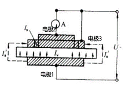
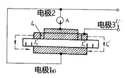
Figure 3: Electrode connection diagram: (A) Testing of volume resistivity (B) Testing of surface resistivity
For the testing of surface resistivity, the electrode connection is as shown in Figure 3 (B): the bottom electrode 1 and the measuring electrode 2 are at the same potential, so there is no current between the measuring electrode 2 and the bottom electrode 1. The current flowing through ammeter A is only the surface current Is between the ring electrode 3 and the measuring electrode 2, so U/Is gives the measured resistance R of the insulating surface between the sample’s ring gap. Thus:
Surface resistivity σ (MΩ):
σ = (R·P) / D
Where R is the measured resistance (MΩ), P is the effective perimeter of the electrode (cm), and D is the width of the measuring gap (cm).
Our company generally adopts the following sample treatment conditions: (1) Humidity conditions and high-temperature environment. Humidity conditions involve treating the samples at 90% relative humidity and 35°C for 96 hours (96/35/90). (2) The high-temperature environment usually involves treating the samples at 125°C for 24 hours (24/125). Other conditions, such as cyclic humidity and heat, direct testing at high temperatures, and salt spray testing, can be conducted based on the application requirements of the materials.
04
Resistivity of Hydrocarbon Substrates
The following figure shows the volume resistivity of ordinary epoxy glass fiber substrates at different temperatures.
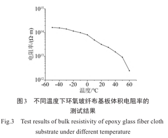
Image source: Chen Yifeng, Yuan Xiaoping, Mei Fei, et al. “Testing of Volume Resistivity of Epoxy Glass Fabric Substrates at Different Temperatures and Study of Internal Charge Effects” [J]. Insulating Materials, 2023, 56(06): 94-99. DOI:10.16790/j.cnki.1009-9239.im.2023.06.015.
The volume resistivity of ordinary epoxy substrates is approximately 1012-1015 Ω·cm, and the surface resistivity is between 1011-1012 Ω. In some special cases, such as in an 85% humidity + salt spray environment, the surface resistivity of epoxy substrates can drop sharply from 1015 Ω·cm to 1012 Ω·cm. This is due to the strong polarity and moisture absorption characteristics of epoxy resin.
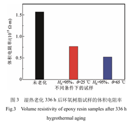
Image source: Li Yafeng, Yao Xueling, Sun Jinru, et al. “Moisture and Heat Aging Characteristics of Epoxy Resin Curing Agents for Insulation Packaging” [J]. High Voltage Technology, 2021, 47(10): 3600-3607. DOI:10.13336/j.1003-6520.hve.20200929.
Hydrocarbon materials themselves possess good insulation properties and low water absorption rates. Their volume resistivity can typically reach above 1014 Ω·cm, and surface resistivity can also reach above 1013 Ω. For example, the TL series of hydrocarbon-based high-frequency copper-clad laminates from Turbulence Electronics (Dk 2.55 — Dk 6.15) generally have a volume resistivity of 1016-1018 Ω·cm, and their surface resistivity can reach 1015-1017 Ω. Notably, under humid and hot conditions, the volume resistivity and surface resistivity of Turbulence Electronics’ hydrocarbon-based high-frequency boards are higher than those of epoxy boards, making them perform better in terms of insulation properties.
