In the field of industrial automation, Siemens PLCs hold a significant position due to their excellent performance and stability. S7 communication, as a key method for data exchange between Siemens PLCs, is crucial for building complex automation systems. For engineers and enthusiasts, mastering the simulation of S7 communication allows for thorough testing and validation before actual hardware setup, greatly enhancing project development efficiency. Today, follow our tutorial to simulate Siemens PLC S7 communication step by step using TIA Portal.
1. Preparation: Software Installation and New Project Creation
Software Installation
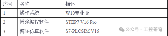
- TIA Portal Software: Ensure that your computer has the appropriate version of TIA Portal (TIA Portal) programming software installed, such as STEP7 V16 Pro or higher. Follow the prompts during the installation process, and make sure to include the S7-PLCSIM simulation software module when selecting components.
- S7-PLCSIM Simulation Software: If S7-PLCSIM was not automatically installed during the TIA Portal installation, you can download the corresponding version from Siemens’ official channels and install it. After installation, it should be found in the TIA Portal startup items.
Create a New Project
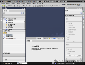
- Open TIA Portal, click “Create New Project”. In the pop-up window, name the project, for example, “Siemens PLC_S7 Communication Simulation”, and select the project save path, then click “Create”. At this point, a brand new project is established, which serves as the basic framework for subsequent operations.
2. Building a Virtual PLC Environment: Adding Devices and Data Blocks
Add Virtual PLC Devices
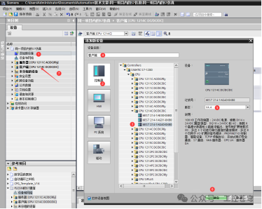
- In the project tree, right-click on “Devices and Networks” and select “Add New Device”. In the device selection window, expand the “Controller” option and choose the Siemens PLC model according to actual needs, such as the CPU1214C from the S7-1200 series. After selection, set the device name, such as “PLC1”, and specify the firmware version (it is recommended to choose version V4.0 or higher to ensure functional support), then click “OK” to complete the addition. Repeat the above steps to add another PLC device, naming it “PLC2”, and you can choose the same or a different model, such as the CPU1511C from the S7-1500 series. This way, we have two virtual PLCs for S7 communication simulation.
Create Data Blocks (DB Blocks)
- For PLC1, find “Program Blocks” in the project tree, right-click, and select “Add New Block”. In the pop-up block type selection window, choose “Data Block (DB)” and name it “DB1_PLC1”, then click “OK”. Similarly, add a data block for PLC2, naming it “DB1_PLC2”.
- Double-click to open DB1_PLC1, and uncheck the “Optimized Block Access” option. This step is crucial because non-optimized block access allows us to use absolute addressing, facilitating data read and write operations in S7 communication. Next, add the data variables to be transmitted in the data block, such as creating a byte array named “SendData” with a length of 10 to store the data to be sent; also create a byte array named “ReceiveData” with the same length of 10 to receive data sent from the other PLC. Configure the data block in DB1_PLC2 in a similar manner.
- 3. Establishing Communication Connection: Configuring Network and Communication Parameters
Network Connection Settings
- Click on the “Devices and Networks” option under the project root directory to enter the network view interface. Here, we can visually see the added PLC1 and PLC2 device icons.
- Select the “Connection” tool from the toolbar, and in the connection type dropdown menu, select “S7 Connection”. Then, click on the PLC1 device icon, and then click on the PLC2 device icon; this will automatically establish an S7 connection line between the two. This is like building a “highway” for data transmission between the two PLCs.
PLC Communication Property Settings
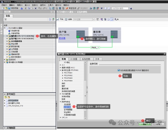
- Double-click the S7 connection line to open the “S7 Connection Properties” window. In the “General” tab, confirm the connection partner information, namely the device names and IP addresses of PLC1 and PLC2. If the IP addresses are not automatically assigned, they need to be set manually, ensuring both PLCs are on the same subnet.
- Switch to the “Local ID” tab, where the ID number of the communication connection is displayed; keep the default settings. This ID number will be used in subsequent programming.
- Click on the PLC1 and PLC2 device icons respectively to enter the device property settings interface. In the “Protection and Security” or “Connection Mechanism” options, check “Allow PUT/GET communication access from remote objects”. This operation is like opening a “door” that allows data transmission between the two PLCs.
4. Writing Communication Programs: Using GET and PUT Instructions
Understanding GET and PUT Instructions
In S7 communication, the GET instruction is used to read data from a remote PLC, while the PUT instruction is used to write data to a remote PLC. They are key tools for achieving data interaction.
Writing Send and Receive Programs
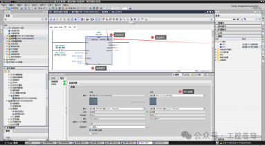
- Open the Main (OB1) program block of PLC1, in the instruction tab, expand “Communication” > “S7 Communication”, and drag the GET instruction into the program editing area. Select the GET instruction, right-click and choose “Properties”, then click “Configuration” in the pop-up window. In the configuration interface, set the “Connection ID” to match the local ID in the previous S7 connection properties; select “Remote Partner” as PLC2; and select the “Data Area” as the area used for sending data in PLC2, such as the “SendData” array in DB1_PLC2. After setting, click “OK”. This way, PLC1 is enabled to read data from PLC2.
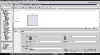
- Similarly, in OB1 of PLC1, drag the PUT instruction into the program editing area. Configure the PUT instruction with the same method as the GET instruction, setting the “Connection ID”, “Remote Partner” (PLC2), and “Data Area” (the area used for sending data in PLC1, such as the “SendData” array in DB1_PLC1). Through the PUT instruction, PLC1 can write data to PLC2.
- Following the above steps, in the Main (OB1) program block of PLC2, also add GET and PUT instructions and configure them accordingly, but this time select PLC1 as the remote partner and choose the corresponding data block area in PLC1. In this way, a bidirectional data transmission program logic is established between the two PLCs.
5. Start Simulation: Witness Data Interaction
Start the PLCSIM Simulator
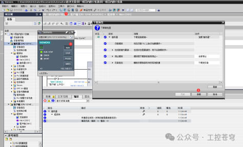
- Return to the main project interface and click the “Start Simulation” button in the toolbar. At this point, the S7-PLCSIM simulator will start. In the simulator interface, click the “Start Search” button and wait for the PLC1 device to be found; after selecting it, click “Download” to download PLC1’s program to the simulator. After downloading, switch PLC1 to “RUN” mode.
- Click the “Start Search” button in the simulator again to find the PLC2 device, and download PLC2’s program to the simulator in the same way as PLC1, then switch to “RUN” mode. At this point, both virtual PLCs are running in the simulation environment.
Monitor Data Transmission
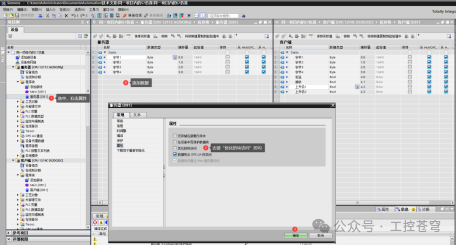
- In the TIA Portal project, select the dual view mode and open the monitoring windows for the data blocks of PLC1 and PLC2 (DB1_PLC1 and DB1_PLC2).
- In the data block DB1_PLC1 of PLC1, modify a piece of data in the “SendData” array, for example, change the first byte’s data from the default value to 16#12. Then, observe the corresponding position in the “ReceiveData” array of PLC2’s data block DB1_PLC2; you should see it change to 16#12, indicating that the data has been successfully sent from PLC1 to PLC2.
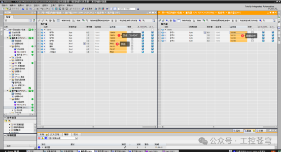
- Conversely, in the data block DB1_PLC2 of PLC2, modify the data in the “SendData” array, for example, change the second byte to 16#34, and check the corresponding position in the “ReceiveData” array of PLC1’s data block DB1_PLC1; the data should also be updated to 16#34. Through this bidirectional testing, we have verified the normal operation of S7 communication in the simulation environment.
Through the above steps, we have successfully completed the S7 communication simulation of Siemens PLC using TIA Portal. This not only helps everyone gain a deeper understanding of S7 communication principles but also accumulates valuable experience for PLC communication debugging in actual projects. What issues did you encounter during the simulation process? Or do you have any new discoveries? Feel free to share and discuss in the comments section.