1. Startup ModesIn the STM32F10xx, different startup modes can be selected through the BOOT[1:0] pins, with BOOT0 and BOOT1 selection pins. The three modes are as follows:
| BOOT1 | BOOT0 | Startup Mode | Description |
| X | 0 | Main Flash Memory | Main Flash Memory is selected as the startup area |
| 0 | 1 | System Memory | System Memory is selected as the startup area |
| 1 | 1 | Built-in SRAM | Built-in SRAM is selected as the startup area |
BOOT1 being X means it can be any value, either 0 or 1. BOOT1 and BOOT0 can be selected by shorting the jumper cap to 0 (GND) or 1 (VCC). The following diagram shows the STM32F103C8T6 as an example, where both BOOT1 and BOOT0 are shorted to GND, which means using the first startup mode, the main flash memory.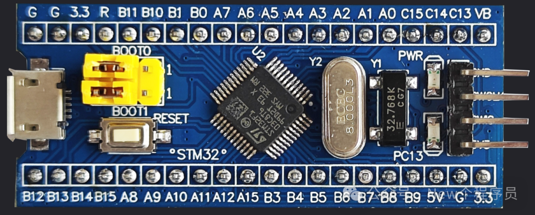 After the system reset, at the 4th rising edge of SYSCLK (system clock frequency), the value of the BOOT pin will be latched. Users can select the startup mode after reset by setting the states of BOOT1 and BOOT0 pins. After reset, the first thing done is: 1. Fetch the initial value of the stack pointer MSP from address 0x0000 0000, which is the top address of the stack. 2. Fetch the initial value of the program counter pointer PC from address 0x0000 0004, which is the reset vector, and this value is the Reset_Handler reset interrupt handler.Here, the address of PC is 4 bytes higher than that of MSP because STM32 is 32-bit, and one address stores a data unit of one byte, which is 8 bits, so the address is incremented by 4.The chip manufacturer can map addresses 0x0000 0000 and 0x0000 0004 to other addresses, as shown in the following diagram.
| BOOT1 | BOOT0 | Startup Mode | 0x0000 0000 Mapped Address | 0x0000 0004 Mapped Address |
| X | 0 | Main Flash Memory | 0x08000000 | 0x80000004 |
| 0 | 1 | System Memory | 0x1FFFF000 | 0x1FFFF004 |
| 1 | 1 | Built-in SRAM | 0x20000000 | 0x20000004 |
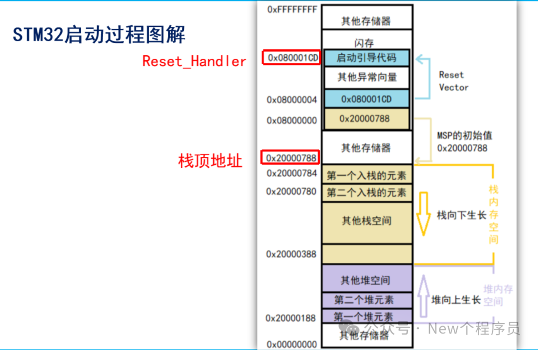
The above are the mapped addresses. If the main flash memory is selected as the startup mode, then the stack top address is fetched from 0x0800 0000, and code execution starts from the address indicated by the startup memory at 0x0000 0004.2. Startup ProcessFirst is the startup file, as follows: 1. Initialize MSP; 2. Initialize PC; 3. Set stack size, Heap_Size (heap), Stack_Size (stack), which can be viewed in the STM32 startup file, as shown below;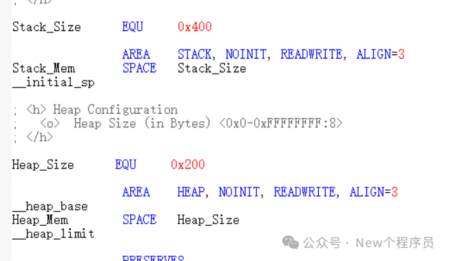 4. Initialize the interrupt vector table, __Vectors definition, which can also be viewed in the STM32 startup file; the first is the stack top address, and the second is the reset vector, which is the reset interrupt function;
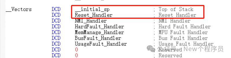 5. Call initialization functions: optional, such as calling the SystemInit function; 6. Call __main: after executing a series of setups, finally call the main function.Then the startup process is as shown in the following diagram, referencing the ZLG, where 0x080001CD and 0x20000788 are viewed in the .map file, which can be found in the project; this 0x20000788 may vary in different projects.