

RFID (Radio Frequency Identification) is a non-contact automatic identification technology that uses radio frequency signals to automatically identify target objects and obtain relevant data. It is widely used in logistics, retail, transportation, healthcare, and many other fields. The following is a detailed introduction from the aspects of technical principles, components, application scenarios, and advantages and disadvantages:
1
Basic Principles of RFID Technology
RFID technology utilizes radio waves for data transmission and communication. Its core principle is electromagnetic induction or electromagnetic backscatter coupling: when an RFID tag enters the magnetic or electromagnetic field generated by a reader, the tag receives the radio frequency signal emitted by the reader, obtaining energy through induced current (passive tags) or actively transmitting signals (active tags) to send stored information back to the reader, completing the identification process.
2
Components of an RFID System
An complete RFID system typically includes the following three core components:
(1) RFID Tag: Equivalent to an “electronic tag”, it contains a chip and antenna for storing identification information of the target object (such as unique ID, item attributes, etc.). Depending on the power supply method, it can be classified as: passive tags (no battery, rely on the reader’s radio frequency energy to operate, low cost, small size, but short communication distance); active tags (with a built-in battery, can actively transmit signals, long communication distance, but high cost, larger size, and battery life limited); semi-active tags (battery only activates the tag, communication still relies on reader energy, balancing distance and cost).
(2) RFID Reader: Responsible for emitting radio frequency signals, receiving information returned from tags, and transmitting data to the backend system. It typically includes an antenna, radio frequency module, and data processing unit, and can be fixed (e.g., access control, warehouse) or handheld (e.g., inventory, inspection).
(3) Backend System: Includes databases, servers, and application software for processing data transmitted from the reader, achieving information storage, querying, analysis, and management (e.g., inventory statistics, trajectory tracking, etc.).
3
Typical Application Scenarios of RFID
(1) Logistics and Supply Chain Management: Achieving full tracking of goods: RFID tags are affixed to containers and packages, allowing for quick identification of goods information through readers, improving sorting efficiency and inventory accuracy. For example, Amazon warehouses utilize RFID for rapid inventory checks, reducing manual operations.
(2) Retail and Inventory Management: After affixing tags to store products, handheld readers can quickly inventory stock, avoiding the cumbersome manual scanning; it can also achieve “contactless checkout” (e.g., self-checkout stations automatically identify products and settle accounts).
(3) Transportation and Access Control: Highway ETC: Vehicles install RFID tags, which are automatically identified and charged at toll booths without stopping; access control systems: employees wear RFID cards, which can open doors by approaching the reader, replacing traditional keys.
(4) Healthcare: Patient wristbands: store patient identity and medical record information, allowing doctors to quickly retrieve data by scanning, reducing human error; medical device tracking: affixing tags to surgical instruments and medications to ensure compliance with disinfection processes and avoid loss.
(5) Anti-counterfeiting and Traceability: Luxury goods, tobacco, and alcohol products are affixed with unique RFID tags, allowing consumers to verify authenticity and production processes through dedicated devices, preventing counterfeiting.
(6) Animal Husbandry and Agriculture: Implanting low-frequency RFID tags in livestock to record growth information and health status, achieving full lifecycle management; agricultural product traceability: recording planting, processing, and transportation information through tags to ensure food safety.
4
Advantages and Disadvantages of RFID
Advantages: Non-contact identification; simultaneous reading of multiple tags; large storage capacity; strong durability; high security.
Disadvantages: Higher cost; susceptible to interference; lack of unified standards; privacy risks.
5
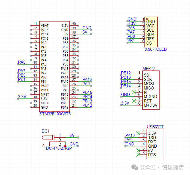
Microcontroller Connection Hardware Diagram
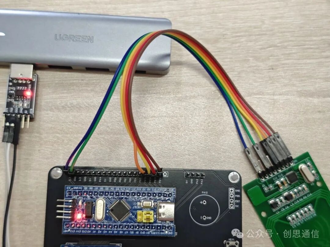
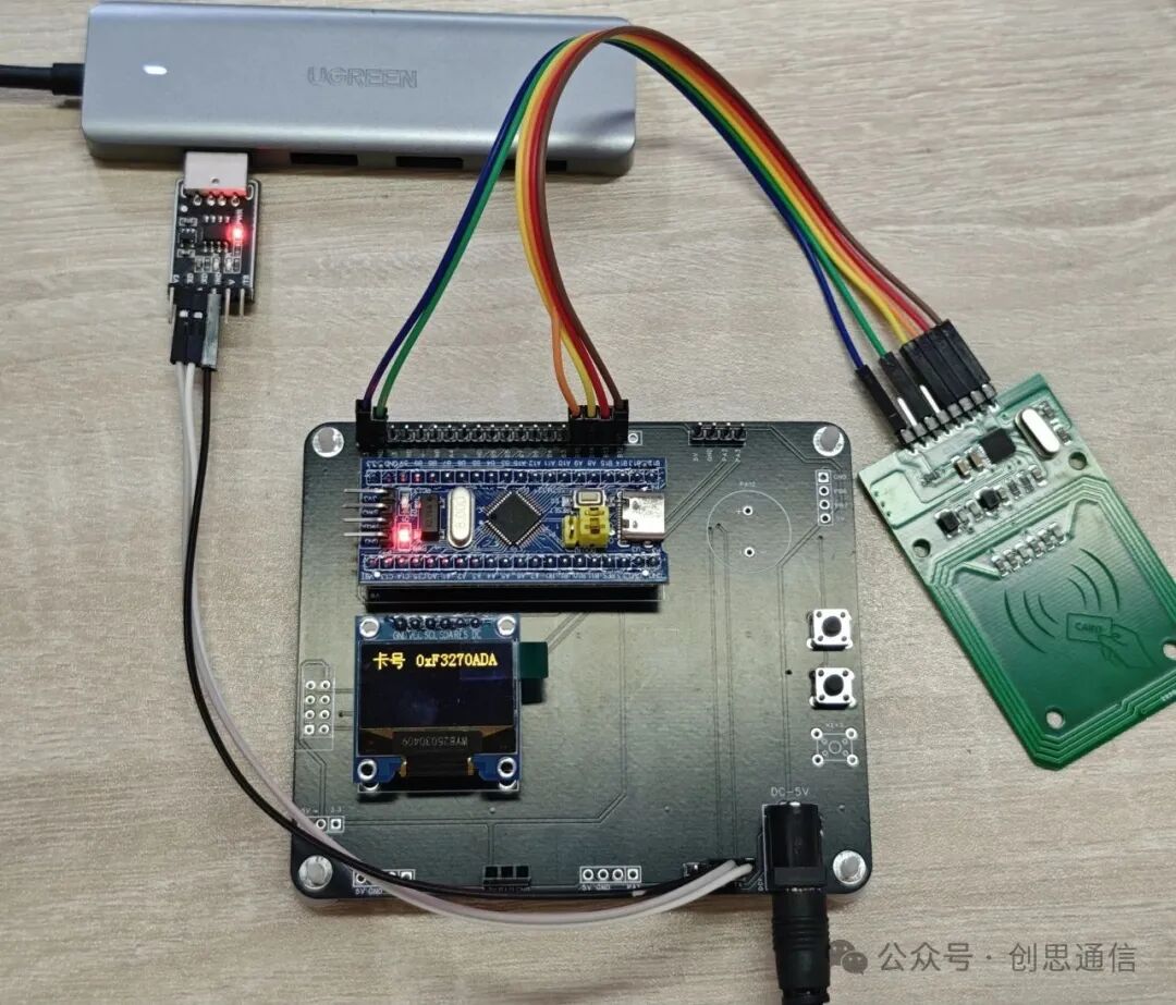
Physical Diagram
6
Driving Ideas
(1) After completing the hardware connection, start the initialization work. First, configure GPIO, set the SPI-related pins to multiplex push-pull output, and set the chip select and reset pins to push-pull output. Then initialize the SPI peripheral, set STM32 to SPI master mode, with a baud rate not exceeding 10MHz, using mode 0 (CPOL=0, CPHA=0) and 8-bit data format. Finally, operate the registers to put the RC522 into the initial state.
(2) Since all functions of the RC522 are implemented through register operations, it is necessary to encapsulate functions for reading and writing registers. When writing to a register, first pull the chip select low, send the register address (the first 4 bits are the address, the last 4 bits are the write command “0010”) and data, then pull the chip select high; reading a register is similar, except the last 4 bits of the address are the read command “0011”, send it and read the returned data. After completing the basic register operations, perform core configurations for the module, such as setting the receive gain through the RegRxGain register to adjust the signal reception strength, configuring the operating frequency to match the module with the card for communication, and initializing the antenna to ensure it can transmit and receive radio frequency signals normally.
(3) Next, implement the card operation process, starting with card searching by sending a card search command (e.g., 0x26) to detect if a card enters the magnetic field. If successful, obtain the card type; then perform anti-collision processing by sending an anti-collision command (e.g., 0x93) to resolve the issue of multiple cards existing simultaneously, obtaining the unique ID of the card; after that, select the card to confirm which card to operate on; if data reading and writing is needed, password verification must also be performed, and only after successful verification can the corresponding data blocks of the M1 card be read and written. Throughout the process, continuously interact with the RC522 via SPI communication of the STM32, outputting the operation results through serial port or other means.
7
Microcontroller Program Code
main.c
#include "stm32f10x.h"
#include "string.h"
#include "stdio.h"
#include "delay.h"
#include "bsp_usart.h"
#include "oled.h"
#include "SPI.h"
#include "RC522.h"

char OLEDBUff[512];
uint8_t cardID[4] = {0};
int main(void)
{
    NVIC_PriorityGroupConfig (NVIC_PriorityGroup_2);
    SysTick_Init(72);  //System clock initialization
    usart1_init(115200);//Serial port 1 initialization
    printf("USART1 OK!\r\n");
    usart2_init(115200);//Serial port 2 initialization
    usart3_init(115200);//Serial port 3 initialization
    OLED_Init();
    SPIClass.SPI2_Init(); // SPI initialization
    MFRC522_Init(); // RC522 initialization
    while(1)
    {
        memset(OLEDBUff,0,512);
        OLED_ShowString(0,0,"Card Number");
        if(RC522_cardScan(cardID)==0)
        {
            sprintf(OLEDBUff,"0x%02X%02X%02X%02X", cardID[0], cardID[1], cardID[2], cardID[3]);
          printf("card scan success, id:0x%02X%02X%02X%02X\n", cardID[0], cardID[1], cardID[2], cardID[3]);
        }
        delay_ms(10);
        OLED_ShowString(42,0,OLEDBUff);
    }
}
Uart.c
#include "stm32f10x.h"
#include "bsp_usart.h"
#include "stdio.h"
#include "string.h"
#include "stm32f10x_tim.h"


//////////////////////////////////////////////////////////////////////////////////

//////////////////////////////////////////////////////////////////
//Add the following code to support printf function without selecting use MicroLIB
#if 1
#pragma import(__use_no_semihosting)
//Standard library required support functions
struct __FILE
{
    int handle;
};

FILE __stdout;
//Define _sys_exit() to avoid using semi-hosting mode
int _sys_exit(int x)
{
    x = x;
    return 0;
}
//Redefine fputc function
int fputc(int ch, FILE *f)
{
    while((USART1->SR&0X40)==0);//Loop sending until finished
    USART1->DR = (u8) ch;
    return ch;
}
#endif

#if EN_USART1

UART_BUF buf_uart1;     //CH340
//Initialize IO Serial Port 1
//bound: Baud rate
void usart1_init(u32 bound){
   //GPIO port settings
  GPIO_InitTypeDef GPIO_InitStructure;
    USART_InitTypeDef USART_InitStructure;
    NVIC_InitTypeDef NVIC_InitStructure;

    RCC_APB2PeriphClockCmd(RCC_APB2Periph_USART1|RCC_APB2Periph_GPIOA, ENABLE);    //Enable USART1, GPIOA clock
    USART_DeInit(USART1);  //Reset serial port 1
//USART1_TX   PA.9
    GPIO_InitStructure.GPIO_Pin = GPIO_Pin_9; //PA.9
    GPIO_InitStructure.GPIO_Speed = GPIO_Speed_50MHz;
    GPIO_InitStructure.GPIO_Mode = GPIO_Mode_AF_PP;    //Multiplex push-pull output
    GPIO_Init(GPIOA, &GPIO_InitStructure); //Initialize PA9

    //USART1_RX      PA.10
    GPIO_InitStructure.GPIO_Pin = GPIO_Pin_10;
    GPIO_InitStructure.GPIO_Mode = GPIO_Mode_IPU;//Floating input
    GPIO_Init(GPIOA, &GPIO_InitStructure);  //Initialize PA10

//USART Initialization settings

    USART_InitStructure.USART_BaudRate = bound;//Generally set to 115200;
    USART_InitStructure.USART_WordLength = USART_WordLength_8b;//Data length is 8 bits
    USART_InitStructure.USART_StopBits = USART_StopBits_1;//One stop bit
    USART_InitStructure.USART_Parity = USART_Parity_No;//No parity bit
    USART_InitStructure.USART_HardwareFlowControl = USART_HardwareFlowControl_None;//No hardware data flow control
    USART_InitStructure.USART_Mode = USART_Mode_Rx | USART_Mode_Tx;    //Receive and transmit mode
    USART_Init(USART1, &USART_InitStructure); //Initialize serial port

    USART_Cmd(USART1, ENABLE);                    //Enable serial port

    #if EN_USART1_RX
    USART_ITConfig(USART1, USART_IT_RXNE, ENABLE);//Enable related interrupts
    USART_ITConfig(USART1, USART_IT_IDLE, ENABLE);//Enable related interrupts
    USART_ClearFlag(USART1, USART_FLAG_TC);
    //Usart1 NVIC configuration
  NVIC_InitStructure.NVIC_IRQChannel = USART1_IRQn;//Serial port 1 interrupt channel
    NVIC_InitStructure.NVIC_IRQChannelPreemptionPriority=3;//Preemption priority 3
    NVIC_InitStructure.NVIC_IRQChannelSubPriority =3;        //Sub-priority 3
    NVIC_InitStructure.NVIC_IRQChannelCmd = ENABLE;            //IRQ channel enable
    NVIC_Init(&NVIC_InitStructure);    //Initialize VIC registers according to specified parameters

    #endif
}

/*********************************Serial Port 1 Service Function*************************************************/
void USART1_Send_byte(char data)
{
    while(USART_GetFlagStatus(USART1, USART_FLAG_TXE) == RESET);
    USART_SendData(USART1, data);
}
/*-------------------------------------------------*/
/*Function Name: Serial Port 1 Send Array                             */
/*Parameters: bound: Baud rate                             */
/*Return Value: None                                        */
/*-------------------------------------------------*/
void USART1_Send(char *Data,uint16_t Len)
{
    uint16_t i;
    for(i=0; i<len; 1="" data="" i++)="" port="" print="" serial="" usart1_send_byte(data[i]);="" usart1_sendstr(char*sendbuf)="" void="" while((usart1-="" while(*sendbuf)="" {="" }="">SR&0X40)==0);//Wait for sending to complete
        USART1->DR = (u8) *SendBuf;
                SendBuf++;
    }
}

/*****************************************************
Clear the buffer data returned by the computer Serial Port 1
*****************************************************/
void Clear_Buffer_UART1(void)//Clear cache
{
    buf_uart1.index=0;
      buf_uart1.rx_flag=0;
    memset(buf_uart1.buf,0,BUFLEN);
}
void UART1_receive_process_event(char ch )     //Serial port 2 for 4G use
{
    if(buf_uart1.index >= BUFLEN)
    {
        buf_uart1.index = 0 ;
    }
    else
    {
        buf_uart1.buf[buf_uart1.index++] = ch;
    }
}

//Serial port 1 receive interrupt program
void USART1_IRQHandler(void)                                //Serial port 1 interrupt service program
{
        uint8_t Res;
        Res=Res;
    if(USART_GetITStatus(USART1, USART_IT_RXNE) != RESET)  //Receive interrupt, can be expanded to control
    {
        Res=USART_ReceiveData(USART1);//Receive data from the module;

        UART1_receive_process_event(Res);//Receive data from the module
    }
    if(USART_GetITStatus(USART1, USART_IT_IDLE) != RESET)  //Module idle
    {
        Res=USART_ReceiveData(USART1);//Receive data from the module;

                buf_uart1.rx_flag=1;
    }
}

#endif

#if EN_USART2
UART_BUF buf_uart2;     //EC200T
//Initialize IO Serial Port 2
//pclk1:PCLK1 clock frequency (Mhz)
//bound: Baud rate
void usart2_init(u32 bound)
{

    GPIO_InitTypeDef GPIO_InitStructure;
    USART_InitTypeDef USART_InitStructure;
    NVIC_InitTypeDef NVIC_InitStructure;

        RCC_APB2PeriphClockCmd(RCC_APB2Periph_GPIOA, ENABLE);    //Enable, GPIOA clock
        RCC_APB1PeriphClockCmd(RCC_APB1Periph_USART2,ENABLE);//USART2
        USART_DeInit(USART2);  //Reset serial port 2
     //USART2_TX   PA.2
    GPIO_InitStructure.GPIO_Pin = GPIO_Pin_2; //PA.2
    GPIO_InitStructure.GPIO_Speed = GPIO_Speed_50MHz;
    GPIO_InitStructure.GPIO_Mode = GPIO_Mode_AF_PP;    //Multiplex push-pull output
    GPIO_Init(GPIOA, &GPIO_InitStructure); //Initialize PA2

    //USART2_RX      PA.3
    GPIO_InitStructure.GPIO_Pin = GPIO_Pin_3;
    GPIO_InitStructure.GPIO_Mode = GPIO_Mode_IN_FLOATING;//Floating input
    GPIO_Init(GPIOA, &GPIO_InitStructure);  //Initialize PA3


   //USART Initialization settings

        USART_InitStructure.USART_BaudRate = bound;//115200
        USART_InitStructure.USART_WordLength = USART_WordLength_8b;//Data length is 8 bits
        USART_InitStructure.USART_StopBits = USART_StopBits_1;//One stop bit
        USART_InitStructure.USART_Parity = USART_Parity_No;//No parity bit
        USART_InitStructure.USART_HardwareFlowControl = USART_HardwareFlowControl_None;//No hardware data flow control
        USART_InitStructure.USART_Mode = USART_Mode_Rx | USART_Mode_Tx;    //Receive and transmit mode
    USART_Init(USART2, &USART_InitStructure); //Initialize serial port
    USART_Cmd(USART2, ENABLE);                    //Enable serial port


#if EN_USART2_RX
    USART_ITConfig(USART2, USART_IT_RXNE, ENABLE);//Enable related interrupts
        USART_ITConfig(USART2, USART_IT_IDLE, ENABLE);//Enable related interrupts

    //Usart1 NVIC configuration
    NVIC_InitStructure.NVIC_IRQChannel = USART2_IRQn;//Serial port 1 interrupt channel
    NVIC_InitStructure.NVIC_IRQChannelPreemptionPriority=0;//Preemption priority 3
    NVIC_InitStructure.NVIC_IRQChannelSubPriority =1;        //Sub-priority 3
    NVIC_InitStructure.NVIC_IRQChannelCmd = ENABLE;            //IRQ channel enable
    NVIC_Init(&NVIC_InitStructure);    //Initialize VIC registers according to specified parameters
#endif
}

void Clear_Buffer_UART2(void)//Clear cache
{
    buf_uart2.index=0;
      buf_uart2.rx_flag=0;
    memset(buf_uart2.buf,0,BUFLEN);
}

/*********************************Serial Port 2 Service Function*************************************************/
void USART2_Send_byte(char data)
{
    while(USART_GetFlagStatus(USART2, USART_FLAG_TXE) == RESET);
    USART_SendData(USART2, data);
}


/*-------------------------------------------------*/
/*Function Name: Serial Port 2 Send Array                             */
/*Parameters: bound: Baud rate                             */
/*Return Value: None                                        */
/*-------------------------------------------------*/
void USART2_Send(char *Data,uint16_t Len)
{
    uint16_t i;
    for(i=0; i<len; 1="" data="" i++)="" port="" print="" serial="" usart2_send_byte(data[i]);="" usart2_sendstr(char*sendbuf)="" void="" while((usart2-="" while(*sendbuf)="" {="" }="">SR&0X40)==0);//Wait for sending to complete
        USART2->DR = (u8) *SendBuf;
        SendBuf++;
    }
}


void usart2_receive_process_event(unsigned char ch )     //Serial port 2 for 4G use
{
    if(buf_uart2.index >= BUFLEN)
    {
        buf_uart2.index = 0 ;
    }
    else
    {
        buf_uart2.buf[buf_uart2.index++] = ch;
    }
}
void USART2_IRQHandler(void)                            //Serial port 2 receive function
{
        char Res;
        Res=Res;
    if(USART_GetITStatus(USART2, USART_IT_RXNE) != RESET)  //Receive interrupt, can be expanded to control
    {
        Res=USART_ReceiveData(USART2);//Receive data from the module;
        usart2_receive_process_event(Res);//Receive data from the module
    }
    if(USART_GetITStatus(USART2, USART_IT_IDLE) != RESET)  //Module idle
    {
        Res=USART_ReceiveData(USART2);//Receive data from the module;
        buf_uart2.rx_flag=1;
         }
}

#endif

#if EN_USART3

UART_BUF buf_uart3;     //TTL
void usart3_init(u32 bound)
{
    //GPIO port settings
    GPIO_InitTypeDef GPIO_InitStructure;
        USART_InitTypeDef USART_InitStructure;
        NVIC_InitTypeDef NVIC_InitStructure;

        RCC_APB2PeriphClockCmd(RCC_APB2Periph_GPIOB, ENABLE);    //Enable, GPIOA clock
        RCC_APB1PeriphClockCmd(RCC_APB1Periph_USART3,ENABLE);//USART3
        USART_DeInit(USART3);  //Reset serial port 3
     //USART3_TX   PB10
    GPIO_InitStructure.GPIO_Pin = GPIO_Pin_10; //PB10
    GPIO_InitStructure.GPIO_Speed = GPIO_Speed_50MHz;
    GPIO_InitStructure.GPIO_Mode = GPIO_Mode_AF_PP;    //Multiplex push-pull output
    GPIO_Init(GPIOB, &GPIO_InitStructure); //Initialize PA2

    //USART3_RX      PB11
    GPIO_InitStructure.GPIO_Pin = GPIO_Pin_11;
    GPIO_InitStructure.GPIO_Mode = GPIO_Mode_IN_FLOATING;//Floating input
    GPIO_Init(GPIOB, &GPIO_InitStructure);  //Initialize PB11

   //USART Initialization settings

        USART_InitStructure.USART_BaudRate = bound;//115200
        USART_InitStructure.USART_WordLength = USART_WordLength_8b;//Data length is 8 bits
        USART_InitStructure.USART_StopBits = USART_StopBits_1;//One stop bit
        USART_InitStructure.USART_Parity = USART_Parity_No;//No parity bit
        USART_InitStructure.USART_HardwareFlowControl = USART_HardwareFlowControl_None;//No hardware data flow control
        USART_InitStructure.USART_Mode = USART_Mode_Rx | USART_Mode_Tx;    //Receive and transmit mode
    USART_Init(USART3, &USART_InitStructure); //Initialize serial port
    USART_Cmd(USART3, ENABLE);                    //Enable serial port

#if EN_USART3_RX
    USART_ITConfig(USART3, USART_IT_RXNE, ENABLE);//Enable related interrupts
    USART_ITConfig(USART3, USART_IT_IDLE, ENABLE);//Enable related interrupts
    USART_ClearFlag(USART3, USART_FLAG_TC);
    //Usart3 NVIC configuration
  NVIC_InitStructure.NVIC_IRQChannel = USART3_IRQn;//Serial port 3 interrupt channel
    NVIC_InitStructure.NVIC_IRQChannelPreemptionPriority=1;//Preemption priority 1
    NVIC_InitStructure.NVIC_IRQChannelSubPriority =3;        //Sub-priority 3
    NVIC_InitStructure.NVIC_IRQChannelCmd = ENABLE;            //IRQ channel enable
    NVIC_Init(&NVIC_InitStructure);    //Initialize VIC registers according to specified parameters
#endif

}

void USART3_Send_byte(char data)
{
    while(USART_GetFlagStatus(USART3, USART_FLAG_TXE) == RESET);
    USART_SendData(USART3, data);
}


/*-------------------------------------------------*/
/*Function Name: Serial Port 2 Send Array                             */
/*Parameters: bound: Baud rate                             */
/*Return Value: None                                        */
/*-------------------------------------------------*/
void USART3_Send(char *Data,uint16_t Len)
{
    uint16_t i;
    for(i=0; i<len; 3="" data="" i++)="" port="" print="" serial="" usart3_send_byte(data[i]);="" usart3_sendstr(char*sendbuf)="" void="" while((usart3-="" while(*sendbuf)="" {="" }="">SR&0X40)==0);//Wait for sending to complete
        USART3->DR = (u8) *SendBuf;
        SendBuf++;
    }
}

/*****************************************************
Clear the buffer data returned by the computer Serial Port 1
*****************************************************/
void Clear_Buffer_UART3(void)//Clear cache
{
    buf_uart3.index=0;
      buf_uart3.rx_flag=0;
    memset(buf_uart3.buf,0,BUFLEN);
}
void USART3_receive_process_event(char ch )     //Serial port 2 for 4G use
{
    if(buf_uart3.index >= BUFLEN)
    {
        buf_uart3.index = 0 ;
    }
    else
    {
        buf_uart3.buf[buf_uart3.index++] = ch;
    }
}
void USART3_IRQHandler(void)                                //Serial port 3 interrupt service program
{
        char Res;
        Res=Res;
    if(USART_GetITStatus(USART3, USART_IT_RXNE) != RESET)  //Receive interrupt, can be expanded to control
    {
        Res=USART_ReceiveData(USART3);//Receive data from the module;
        USART3_receive_process_event(Res);
    }
    if(USART_GetITStatus(USART3, USART_IT_IDLE) != RESET)  //Module idle
    {
        Res=USART_ReceiveData(USART3);//Receive data from the module;
                buf_uart3.rx_flag=1;
    }
}

#endif
</len;></len;></len;>
RC522.c
// Mifare RC522 RFID Card reader 13.56 MHz
// MFRC522        STM32F103        DESCRIPTION
// CS (SDA)        PB0                SPI1_NSS    Chip select for SPI
// SCK            PA5                SPI1_SCK    Serial Clock for SPI
// MOSI            PA7             SPI1_MOSI    Master In Slave Out for SPI
// MISO            PA6                SPI1_MISO    Master Out Slave In for SPI
// IRQ            -                Irq
// GND            GND                Ground
// RST            3.3V            Reset pin (3.3V)
// VCC            3.3V            3.3V power
#include "RC522.h"
#include "SPI.h"

#include "bsp_usart.h"
#include "stm32f10x.h"
#include "string.h"
#include "stdio.h"
#include "delay.h"
extern uint8_t cardID[4];
/******template******/
// Convert 0-255 numbers to characters  0xFF--"FF"
void char_to_hex(uint8_t data, uint8_t *retStr) {
    uint8_t digits[16] = {'0','1','2','3','4','5','6','7','8','9','A','B','C','D','E','F'};

    if (data < 16) {
        retStr[0] = '0';
        retStr[1] = digits[data];
    } else {
        retStr[0] = digits[(data & 0xF0)>>4];
        retStr[1] = digits[(data & 0x0F)];
    }
}
/**
  * @brief  Scan RFID card
  * @param  cardID Four-byte array
  * @retval 0 Scan RFID card
  */
uint8_t RC522_cardScan(uint8_t *cardID)
{
    if(!MFRC522_Request(PICC_REQIDL, cardID)) {
        if(!MFRC522_Anticoll(cardID)) {

#ifdef DEBUG_printf
            uint8_t cardIDString[8] = {0};
            for(uint8_t i = 0; i < 4; i++) {
                char_to_hex(cardID[i], cardIDString+i*2);
            }
            printf("card id:%s\n", cardIDString);
#endif
            return 0;
        }
    }
    return 1;
}
/********************/

void SPI1_WriteReg(uint8_t address, uint8_t value) {
    cs_reset();
    SPISendByte(address);
    SPISendByte(value);
    cs_set();
}

uint8_t SPI1_ReadReg(uint8_t address) {
    uint8_t val;

    cs_reset();
    SPISendByte(address);
    val = SPISendByte(0x00);
    cs_set();
    return val;
}

void MFRC522_WriteRegister(uint8_t addr, uint8_t val) {
    addr = (addr << 1) & 0x7E;                                                            // Address format: 0XXXXXX0
SPI1_WriteReg(addr, val);
}

uint8_t MFRC522_ReadRegister(uint8_t addr) {
    uint8_t val;

    addr = ((addr << 1) & 0x7E) | 0x80;
    val = SPI1_ReadReg(addr);
    return val;
}

uint8_t MFRC522_Check(uint8_t* id) {
    uint8_t status;
    status = MFRC522_Request(PICC_REQIDL, id);                            // Find cards, return card type
    if (status == MI_OK) status = MFRC522_Anticoll(id);            // Card detected. Anti-collision, return card serial number 4 bytes
    MFRC522_Halt();                                                                                    // Command card into hibernation
    return status;
}

uint8_t MFRC522_Compare(uint8_t* CardID, uint8_t* CompareID) {
    uint8_t i;
    for (i = 0; i < 5; i++) {
        if (CardID[i] != CompareID[i]) return MI_ERR;
    }
    return MI_OK;
}

void MFRC522_SetBitMask(uint8_t reg, uint8_t mask) {
    MFRC522_WriteRegister(reg, MFRC522_ReadRegister(reg) | mask);
}

void MFRC522_ClearBitMask(uint8_t reg, uint8_t mask){
    MFRC522_WriteRegister(reg, MFRC522_ReadRegister(reg) & (~mask));
}

uint8_t MFRC522_Request(uint8_t reqMode, uint8_t* TagType) {
    uint8_t status;
    uint16_t backBits;                                                                            // The received data bits

    MFRC522_WriteRegister(MFRC522_REG_BIT_FRAMING, 0x07);        // TxLastBists = BitFramingReg[2..0]
    TagType[0] = reqMode;
    status = MFRC522_ToCard(PCD_TRANSCEIVE, TagType, 1, TagType, &backBits);
    if ((status != MI_OK) || (backBits != 0x10)) status = MI_ERR;
    return status;
}

uint8_t MFRC522_ToCard(uint8_t command, uint8_t* sendData, uint8_t sendLen, uint8_t* backData, uint16_t* backLen) {
    uint8_t status = MI_ERR;
    uint8_t irqEn = 0x00;
    uint8_t waitIRq = 0x00;
    uint8_t lastBits;
    uint8_t n;
    uint16_t i;

    switch (command) {
        case PCD_AUTHENT: {
            irqEn = 0x12;
            waitIRq = 0x10;
            break;
        }
        case PCD_TRANSCEIVE: {
            irqEn = 0x77;
            waitIRq = 0x30;
            break;
        }
        default:
        break;
    }

    MFRC522_WriteRegister(MFRC522_REG_COMM_IE_N, irqEn | 0x80);
    MFRC522_ClearBitMask(MFRC522_REG_COMM_IRQ, 0x80);
    MFRC522_SetBitMask(MFRC522_REG_FIFO_LEVEL, 0x80);
    MFRC522_WriteRegister(MFRC522_REG_COMMAND, PCD_IDLE);

    // Writing data to the FIFO
    for (i = 0; i < sendLen; i++) MFRC522_WriteRegister(MFRC522_REG_FIFO_DATA, sendData[i]);

    // Execute the command
    MFRC522_WriteRegister(MFRC522_REG_COMMAND, command);
    if (command == PCD_TRANSCEIVE) MFRC522_SetBitMask(MFRC522_REG_BIT_FRAMING, 0x80);        // StartSend=1,transmission of data starts

    // Waiting to receive data to complete
    i = 2000;    // i according to the clock frequency adjustment, the operator M1 card maximum waiting time 25ms
    do {
        // CommIrqReg[7..0]
        // Set1 TxIRq RxIRq IdleIRq HiAlerIRq LoAlertIRq ErrIRq TimerIRq
        n = MFRC522_ReadRegister(MFRC522_REG_COMM_IRQ);
        i--;
    } while ((i!=0) && !(n&0x01) && !(n&waitIRq));

    MFRC522_ClearBitMask(MFRC522_REG_BIT_FRAMING, 0x80);                                                                // StartSend=0

    if (i != 0)  {
        if (!(MFRC522_ReadRegister(MFRC522_REG_ERROR) & 0x1B)) {
            status = MI_OK;
            if (n & irqEn & 0x01) status = MI_NOTAGERR;
            if (command == PCD_TRANSCEIVE) {
                n = MFRC522_ReadRegister(MFRC522_REG_FIFO_LEVEL);
                lastBits = MFRC522_ReadRegister(MFRC522_REG_CONTROL) & 0x07;
                if (lastBits) *backLen = (n-1)*8+lastBits; else *backLen = n*8;
                if (n == 0) n = 1;
                if (n > MFRC522_MAX_LEN) n = MFRC522_MAX_LEN;
                for (i = 0; i < n; i++) backData[i] = MFRC522_ReadRegister(MFRC522_REG_FIFO_DATA);        // Reading the received data in FIFO
            }
        } else status = MI_ERR;
    }
    return status;
}

uint8_t MFRC522_Anticoll(uint8_t* serNum) {
    uint8_t status;
    uint8_t i;
    uint8_t serNumCheck = 0;
    uint16_t unLen;

    MFRC522_WriteRegister(MFRC522_REG_BIT_FRAMING, 0x00);                                                // TxLastBists = BitFramingReg[2..0]
    serNum[0] = PICC_ANTICOLL;
    serNum[1] = 0x20;
    status = MFRC522_ToCard(PCD_TRANSCEIVE, serNum, 2, serNum, &unLen);
    if (status == MI_OK) {
        // Check card serial number
        for (i = 0; i < 4; i++) serNumCheck ^= serNum[i];
        if (serNumCheck != serNum[i]) status = MI_ERR;
    }
    return status;
}

void MFRC522_CalculateCRC(uint8_t*  pIndata, uint8_t len, uint8_t* pOutData) {
    uint8_t i, n;

    MFRC522_ClearBitMask(MFRC522_REG_DIV_IRQ, 0x04);                                                    // CRCIrq = 0
    MFRC522_SetBitMask(MFRC522_REG_FIFO_LEVEL, 0x80);                                                    // Clear the FIFO pointer
    // Write_MFRC522(CommandReg, PCD_IDLE);

    // Writing data to the FIFO
    for (i = 0; i < len; i++) MFRC522_WriteRegister(MFRC522_REG_FIFO_DATA, *(pIndata+i));
    MFRC522_WriteRegister(MFRC522_REG_COMMAND, PCD_CALCCRC);

    // Wait CRC calculation is complete
    i = 0xFF;
    do {
        n = MFRC522_ReadRegister(MFRC522_REG_DIV_IRQ);
        i--;
    } while ((i!=0) && !(n&0x04));                                                                                        // CRCIrq = 1

    // Read CRC calculation result
    pOutData[0] = MFRC522_ReadRegister(MFRC522_REG_CRC_RESULT_L);
    pOutData[1] = MFRC522_ReadRegister(MFRC522_REG_CRC_RESULT_M);
}

uint8_t MFRC522_SelectTag(uint8_t* serNum) {
    uint8_t i;
    uint8_t status;
    uint8_t size;
    uint16_t recvBits;
    uint8_t buffer[9];

    buffer[0] = PICC_SElECTTAG;
    buffer[1] = 0x70;
    for (i = 0; i < 5; i++) buffer[i+2] = *(serNum+i);
    MFRC522_CalculateCRC(buffer, 7, &buffer[7]);        //??
    status = MFRC522_ToCard(PCD_TRANSCEIVE, buffer, 9, buffer, &recvBits);
    if ((status == MI_OK) && (recvBits == 0x18)) size = buffer[0]; else size = 0;
    return size;
}

uint8_t MFRC522_Auth(uint8_t authMode, uint8_t BlockAddr, uint8_t* Sectorkey, uint8_t* serNum) {
    uint8_t status;
    uint16_t recvBits;
    uint8_t i;
    uint8_t buff[12];

    // Verify the command block address + sector + password + card serial number
    buff[0] = authMode;
    buff[1] = BlockAddr;
    for (i = 0; i < 6; i++) buff[i+2] = *(Sectorkey+i);
    for (i=0; i<4; i++) buff[i+8] = *(serNum+i);
    status = MFRC522_ToCard(PCD_AUTHENT, buff, 12, buff, &recvBits);
    if ((status != MI_OK) || (!(MFRC522_ReadRegister(MFRC522_REG_STATUS2) & 0x08))) status = MI_ERR;
    return status;
}

uint8_t MFRC522_Read(uint8_t blockAddr, uint8_t* recvData) {
    uint8_t status;
    uint16_t unLen;

    recvData[0] = PICC_READ;
    recvData[1] = blockAddr;
    MFRC522_CalculateCRC(recvData,2, &recvData[2]);
    status = MFRC522_ToCard(PCD_TRANSCEIVE, recvData, 4, recvData, &unLen);
    if ((status != MI_OK) || (unLen != 0x90)) status = MI_ERR;
    return status;
}

uint8_t MFRC522_Write(uint8_t blockAddr, uint8_t* writeData) {
    uint8_t status;
    uint16_t recvBits;
    uint8_t i;
    uint8_t buff[18];

    buff[0] = PICC_WRITE;
    buff[1] = blockAddr;
    MFRC522_CalculateCRC(buff, 2, &buff[2]);
    status = MFRC522_ToCard(PCD_TRANSCEIVE, buff, 4, buff, &recvBits);
    if ((status != MI_OK) || (recvBits != 4) || ((buff[0] & 0x0F) != 0x0A)) status = MI_ERR;
    if (status == MI_OK) {
        // Data to the FIFO write 16Byte
        for (i = 0; i < 16; i++) buff[i] = *(writeData+i);
        MFRC522_CalculateCRC(buff, 16, &buff[16]);
        status = MFRC522_ToCard(PCD_TRANSCEIVE, buff, 18, buff, &recvBits);
        if ((status != MI_OK) || (recvBits != 4) || ((buff[0] & 0x0F) != 0x0A)) status = MI_ERR;
    }
    return status;
}

void MFRC522_Init(void) {
    MFRC522_Reset();
    MFRC522_WriteRegister(MFRC522_REG_T_MODE, 0x8D);
    MFRC522_WriteRegister(MFRC522_REG_T_PRESCALER, 0x3E);
    MFRC522_WriteRegister(MFRC522_REG_T_RELOAD_L, 30);
    MFRC522_WriteRegister(MFRC522_REG_T_RELOAD_H, 0);
    MFRC522_WriteRegister(MFRC522_REG_RF_CFG, 0x70);                // 48dB gain
    MFRC522_WriteRegister(MFRC522_REG_TX_AUTO, 0x40);
    MFRC522_WriteRegister(MFRC522_REG_MODE, 0x3D);
    MFRC522_AntennaOn();                                                                        // Open the antenna
}

void MFRC522_Reset(void) {
    MFRC522_WriteRegister(MFRC522_REG_COMMAND, PCD_RESETPHASE);
}

void MFRC522_AntennaOn(void) {
    uint8_t temp;

    temp = MFRC522_ReadRegister(MFRC522_REG_TX_CONTROL);
    if (!(temp & 0x03)) MFRC522_SetBitMask(MFRC522_REG_TX_CONTROL, 0x03);
}

void MFRC522_AntennaOff(void) {
    MFRC522_ClearBitMask(MFRC522_REG_TX_CONTROL, 0x03);
}

void MFRC522_Halt(void) {
    uint16_t unLen;
    uint8_t buff[4];

    buff[0] = PICC_HALT;
    buff[1] = 0;
    MFRC522_CalculateCRC(buff, 2, &buff[2]);
    MFRC522_ToCard(PCD_TRANSCEIVE, buff, 4, buff, &unLen);
}
8
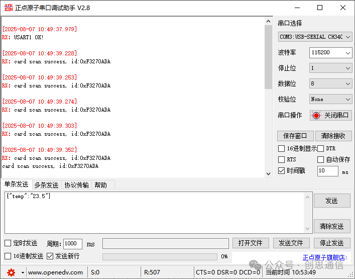
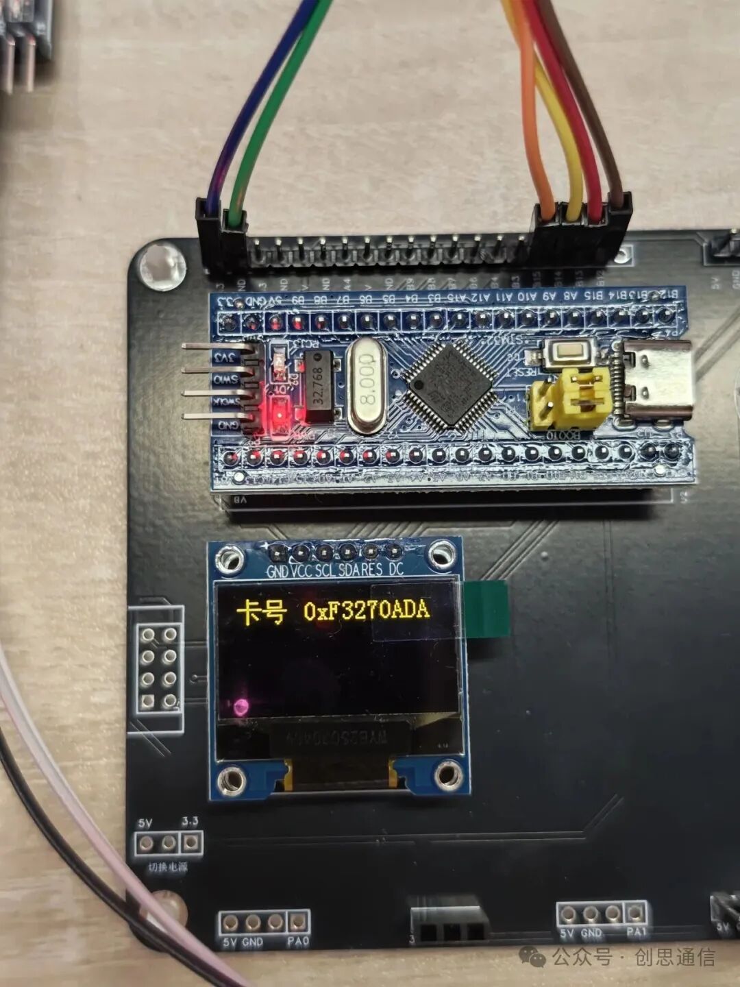
Implementation Effect Images
9
Links
Code Link:
https://download.csdn.net/download/qq_41954594/91610115
Purchase Link: https://item.taobao.com/item.htm?id=36912556969