This collection mainly records some issues encountered in daily work or answers from experts in the verification technology communication group.1. Difference between IP verification environment and SoC environment: The image is from the public account《IC Digital Verification》, feel free to follow this expert’s public account if needed.IP Verification: Focuses on whether the IP module (such as PCIe, USB, DDR, etc.) functions comply with specification standards. The core tasks include functional coverage, interface protocol consistency, power consumption performance, etc. The verification environment typically includes only the IP itself, VIP, stimulus generators, and coverage collection, using the UVM verification platform to generate random + constrained stimuli to cover all functional points and collect code/functional coverage.SoC Verification: Focuses on system integration, verifying the collaborative operation of multiple IPs, such as the system boot process (boot ROM), cross-module data flow, power management, hardware/firmware interaction, etc. Typical issues include whether the CPU can access DDR via the AXI bus, conflicts from multiple IP requests, interrupt handling, etc. The verification environment is highly complex, usually requiring a real CPU, various IPs, clock networks, VIPs, etc., relying on C assembly programs to simulate real CPU application scenarios and drive the entire verification environment.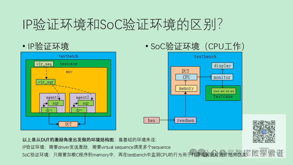 2. How to control the end time of CPU simulation in the SoC verification environment? 1. Add print statements: Convert internal prints of the C program into bus or serial port read/writes; 2. Write a specified value to an idle memory space in the C program, and end the simulation when this value is detected to change. This can also be used for CPU and UVM interaction.3.How to write AHB burst transfer in C code on SoC? Usually, this is done using VIP.In SoC, there needs to be a bus master device that supports burst transfer (such as a DMA controller or an accelerator with a bus interface). The C code configures the control registers of the master device through memory-mapped registers (MMIO).Taking DMA as an example:1. Register address mapping
#define DMA_BASE_ADDR  0x40000000 // Register offset definition
#define DMA_SRC_ADDR   (*(volatile uint32_t*)(DMA_BASE_ADDR + 0x00))
#define DMA_DST_ADDR   (*(volatile uint32_t*)(DMA_BASE_ADDR + 0x04))
#define DMA_LENGTH     (*(volatile uint32_t*)(DMA_BASE_ADDR + 0x08))
#define DMA_CTRL       (*(volatile uint32_t*)(DMA_BASE_ADDR + 0x0C)) // Control register bit definitions
#define DMA_START      (1 << 0)    // Start transfer
#define DMA_BURST_INCR (1 << 1)    // Burst type: INCR
#define DMA_BURST_4    (3 << 4)    // Burst length = 4 beats (AXI protocol: ARLEN/AWLEN=3)
2. Configure and start DMA burst transfer
void dma_burst_transfer(uint32_t src, uint32_t dst, uint32_t byte_len) {
    // 1. Calculate Burst parameters (assuming bus width is 32bit = 4Byte)
    uint32_t burst_length = byte_len / 4;  // Total number of beats
    // 2. Configure registers
    DMA_SRC_ADDR = src;       // Source address (must be 4-byte aligned)
    DMA_DST_ADDR = dst;       // Destination address (must be 4-byte aligned)
    DMA_LENGTH   = burst_length;
    // 3. Set control register: INCR type + Burst length = 4 + Start
    DMA_CTRL = DMA_BURST_INCR | DMA_BURST_4 | DMA_START;
    // 4. Wait for transfer to complete (polling status bit)
    while (DMA_CTRL & DMA_START);
}
3. Call in the C environment
int main() {
    // Test scenario: Burst transfer 128 bytes from memory address 0x80000000 to 0x90000000
    dma_burst_transfer(0x80000000, 0x90000000, 128);
    return 0;
}4.When setting up the environment, the simulation hangs, and I couldn’t find the problem after searching for a long time. What are some good debugging methods?1.Step-by-step debugging with DVE?2.Check each forever begin?3.Open Verdi to see which objections haven’t ended4.It seems that there is a problem with the connection between vseqr and vseq, but the code connection looks fine. Maybe there is an issue here.5.If there are no clues, first comment out all the code in the tasks and release it bit by bit,open the waveform to see if it moves.6.Try VCS + loop report to see if it’s in a dead loop. Run simulation with Verdi’s GUI.7.Generally, it’s either a dead loop, random solving, or a timescale usage issue.8.It could be that the phase hasn’t dropped or some segments haven’t consumed time, causing this.