1. System Overview
This case study designs a lifting control system based on the Siemens S7-1200 PLC, suitable for material lifting equipment in industrial settings. The system adopts a modular programming approach, integrating position closed-loop control, safety interlock protection, and human-machine interaction functions, enabling manual/automatic mode switching, precise positioning, and fault alarm functionalities.
2. System Hardware Composition
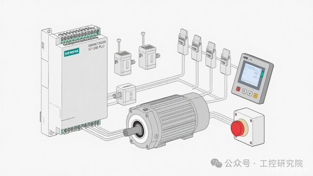
Main Hardware Configuration:
- Controller: Siemens S7-1215C DC/DC/DC (6ES7 215-1AG40-0XB0)
- Drive System: Siemens V90 servo drive + 1.5kW servo motor (with encoder feedback)
- Detection Elements: Laser distance sensor (for real-time position feedback), upper/lower limit switches (mechanical redundancy design)
- Human-Machine Interface: TP1200 intelligent panel (12-inch touchscreen)
- Safety Devices: Emergency stop button (dual-circuit design), fall prevention status sensor, chain slack detection switch
3. I/O Address Allocation
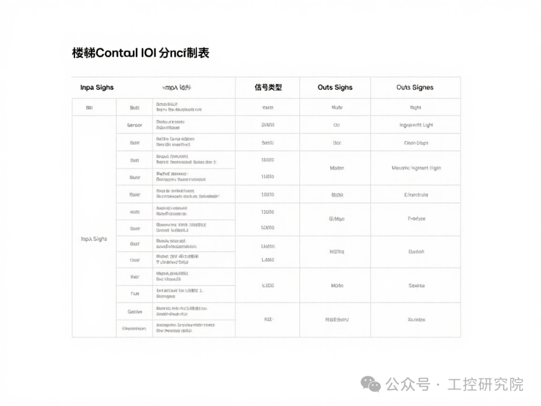
Input Signals (DI):
| Signal Name | Address | Type | Description |
|---|---|---|---|
| Emergency Stop Button | I0.0 | Normally Closed | Hardware safety loop + software detection |
| Up Button | I0.1 | Normally Open | Valid in manual mode |
| Down Button | I0.2 | Normally Open | Valid in manual mode |
| Auto/Manual Switch | I0.3 | Normally Open | High level for automatic mode |
| Upper Limit Switch | I1.0 | Normally Closed | Mechanical + photoelectric dual redundancy |
| Lower Limit Switch | I1.1 | Normally Closed | Mechanical + photoelectric dual redundancy |
| Chain Slack Detection | I1.2 | Normally Open | Chain tension anomaly detection |
| Laser Sensor Ready | I1.3 | Normally Open | Position feedback signal normal |
Output Signals (DO):
| Signal Name | Address | Type | Description |
|---|---|---|---|
| Up Contactor | Q0.0 | Relay | Controls motor forward rotation |
| Down Contactor | Q0.1 | Relay | Controls motor reverse rotation |
| Brake Coil | Q0.2 | Transistor | Motor brake control |
| Running Indicator Light | Q0.3 | LED | Indicates system is running normally |
| Alarm Indicator Light | Q0.4 | LED | Red flashing indicates fault |
| HMI Alarm Buzzer | Q0.5 | Transistor | Sounds alarm on fault |
4. Control Program Design
4.1 Program Architecture
The system program adopts a modular design, mainly consisting of the following organization blocks (OB) and function blocks (FB):
- OB1: Main cycle organization block, responsible for calling various function modules
- OB100: Initialization organization block, system power-on initialization
- FB10:
<span>FB_Positioning</span>Position control function block - FB20:
<span>FB_SafetyCheck</span>Safety interlock function block - FB30:
<span>FB_HMI_Comm</span>HMI data interaction function block
4.2 Control Flow Chart
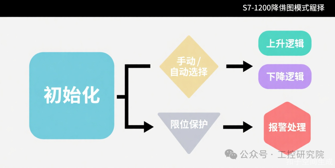
Main Control Flow:
- System Initialization (OB100): Reset axis status, initialize variables, check hardware readiness
- Safety Interlock (FB20): Real-time monitoring of emergency stop, limit, chain slack, and other safety signals
- Mode Selection
- Manual Mode: Directly responds to up/down buttons, jog control
- Automatic Mode: Receives target position set by HMI, automatically completes positioning
4.3 Core Function Block Code Example
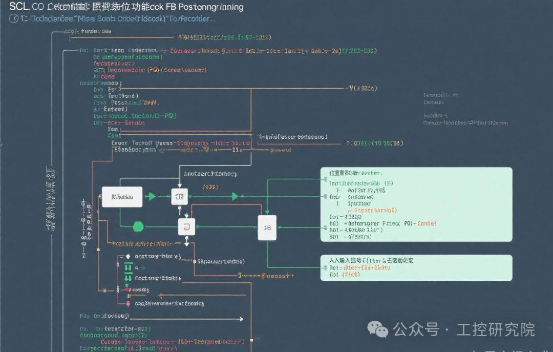
FB_Positioning Position Control Function Block:
FUNCTION_BLOCK FB_Positioning
VAR_INPUT
    CurrentHeight : REAL;    // Current height measurement (mm)
    TargetHeight : REAL;     // Target height (mm)
    Tolerance : REAL := 5.0; // Allowable error (mm)
    Enable : BOOL;           // Function block enable
END_VAR
VAR_OUTPUT
    MoveUp : BOOL;           // Up command
    MoveDown : BOOL;         // Down command
    PositionOK : BOOL;       // Position signal
    Error : BOOL;            // Positioning error
END_VAR
VAR
    ErrorCount : INT;        // Out-of-tolerance count
    TimeoutTimer : TON;      // Position timeout timer
END_VAR

// Position timeout detection
TimeoutTimer(IN := Enable AND NOT PositionOK, PT := T#5S);

// Position closed-loop control logic
IF Enable THEN
    IF ABS(CurrentHeight - TargetHeight) > Tolerance THEN
        MoveUp := CurrentHeight < TargetHeight;
        MoveDown := CurrentHeight > TargetHeight;
        ErrorCount := 0;
        Error := FALSE;

        // Timeout judgment
        IF TimeoutTimer.Q THEN
            Error := TRUE;
            MoveUp := FALSE;
            MoveDown := FALSE;
        END_IF;
    ELSE
        // Confirm position only after 3 consecutive successful detections
        ErrorCount := ErrorCount + 1;
        IF ErrorCount >= 3 THEN
            PositionOK := TRUE;
            MoveUp := FALSE;
            MoveDown := FALSE;
        END_IF;
    END_IF;
ELSE
    // Reset outputs when function block is not enabled
    MoveUp := FALSE;
    MoveDown := FALSE;
    PositionOK := FALSE;
    ErrorCount := 0;
    TimeoutTimer(IN := FALSE);
END_IF;
5. Safety Design Points
-
Dual Safety Loop:
- The emergency stop button is connected to both PLC input and safety relay, achieving dual protection through hardware and software
- The limit switches use normally closed contacts in series to ensure protection is triggered in case of a disconnection
Motor Safety Control:
- The brake coil is linked with the motor drive contactor, immediately braking upon power loss
- The program includes power loss delay detection (500ms) to prevent brake failure from causing slipping
Fault Diagnosis:
- Real-time monitoring of sensor status, triggering alarms on anomalies
- The HMI displays detailed fault codes and troubleshooting guides
6. Debugging and Optimization
-
Sensor Debouncing:
- Laser distance sensor data uses 3-sample average filtering
- Position signal includes 3 consecutive successful judgments to avoid false triggers
PID Parameter Tuning:
- Proportional coefficient (Kp) = 2.0, Integral time (Ti) = 10s, Derivative time (Td) = 1s
- Soft start is used at startup to avoid mechanical shock
HMI Interface Design:
- Real-time display of current height, target height, and operating status
- Trend chart control records 24-hour position change curve
- Hierarchical alarm display: emergency fault (red flashing), warning (yellow), prompt (blue)
7. Application Expansion
This system can be functionally expanded in the following ways:
- Add PROFINET bus interface for multi-axis coordinated control
- Integrate RFID identification for automatic material tracking
- Connect to cloud platform for remote monitoring and data analysis
- Add visual recognition system for automatic material positioning compensation
 Like, Follow + Share!