
Engineers never forget the need to deliver projects that meet quality, schedule, and budget goals. You can draw on the lessons learned from the embedded systems developer community over the years to ensure your next embedded systems project achieves these goals. Below, we will explore some important experiences that have brought best practices to embedded development.
Systematic Thinking
Systems engineering is a broad discipline that encompasses all development work from aircraft carriers and satellites to the embedded systems that realize their performance. We can apply systems engineering methods to manage the embedded systems engineering lifecycle from concept to disposal at the end of its usage cycle. The first phase of a systems engineering approach is different from what most people might imagine; it is not about establishing system requirements but rather about developing a systems engineering management plan. This plan will not only define the engineering lifecycle of the system and the design reviews the development team will undertake but will also define the expected inputs and outputs of these reviews. The plan can provide clear definitions for project management, engineering, and the customer base based on the sequence of engineering events and the prerequisites for each phase.
In short, it can showcase expectations and deliverables. With a clear understanding of the engineering lifecycle, the next step in systematic thinking is to establish the requirements for the embedded system being developed. A good set of requirements should cover three aspects. Functional requirements define how the embedded system will operate. Non-functional requirements define issues such as regulatory compliance and reliability. Environmental requirements define the operational temperature and requirements related to shock and vibration, as well as electrical environments (e.g., EMI and EMC). In larger-scale development work, these requirements will extend down from higher-level specifications and can be traced, such as system or subsystem specifications (Figure 1). Without higher-level specifications, we must engage stakeholders during the development process to establish a clear set of stakeholder requirements, which will then be used to define the embedded system requirements.
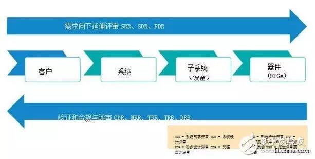
Figure 1 Requirements extend down from higher-level specifications and can be traced
Generating a good set of requirements requires us to think carefully about each requirement to ensure it meets these criteria:
1. It is necessary. Without requirements, our project will not succeed.
2. It is verifiable. We must ensure that the requirement can be achieved through inspection, testing, analysis, or demonstration.
3. It is achievable. The requirement is technically feasible within given constraints.
4. It is traceable. The requirement can be traced from lower-level requirements and can trace higher-level requirements.
5. It is unique. This criterion prevents ambiguity between requirements.
6. It is simple and clear. Each requirement specifies a single function.
To reflect intent, specific language is often used when defining requirements. Generally, we use “must” for mandatory requirements and “should” for non-mandatory requirements. Non-mandatory requirements allow us to express necessary system attributes.
Once we have established our baseline requirements, best practice is to create a compliance matrix that indicates how each requirement is met. We can also begin to establish our verification strategy by assigning a verification method to each requirement. These methods typically include testing, analysis, inspection, demonstration, and cross-reading. Creating requirements based on the compliance and verification matrix allows us to:
-
Clearly understand system behavior.
-
Demonstrate verification methods to both internal testing teams and external customers. This can help identify any difficult testing methods early in the development process and assist in determining the resources needed.
-
Identify technical performance metrics. These metrics come from the compliance matrix and consist of various requirements that pose risks of non-compliance.
Allocating Engineering Budgets
Every engineering project encompasses a certain budget, which we should allocate to the solutions identified in the architecture. Budget allocation not only ensures that the project meets overall requirements but also ensures that each module’s design lead understands the allocation of the module to create appropriate solutions. Typical areas for budget allocation include overall quality of functionality, total power consumption of functionality, reliability defined by mean time between failures or success probability, and legitimate crosstalk between signal types in the design (generally a set of common rules applicable to many functions). One of the most important aspects of establishing an engineering budget is ensuring we have sufficient contingency allocation. However, we must overcome the idea of contingency upon contingency, as this can lead to serious technical issues affecting schedule and cost.
Managing Technical Risks
From the generation of the compliance matrix and engineering budget, we should be able to identify technically challenging requirements. Each of these risky requirements should have a clear mitigation plan that outlines how we will achieve this requirement. One of the best ways to demonstrate this is by using the Technology Readiness Level (TRL). TRL has 9 levels, ranging from observed basic principles (TRL1) to full functionality and field deployment (TRL9), describing the maturity levels of the design. Assigning TRL to each technology used in our architecture, combined with the compliance matrix, can help us identify where technical risks lie. We can then initiate a TRL development plan to ensure that as the project progresses, low TRL areas are elevated to the required TRL level. The content of this plan can ensure that we achieve and test the correct functionality as the project progresses or execute functional or environmental/dynamic testing during the project’s advancement.
Creating Architecture
After understanding the behavior required of the embedded system, we need to create an architecture for the solution. This architecture will consist of requirements grouped into functional blocks. For example, if the embedded system must handle analog inputs or outputs, the architecture will include analog I/O modules. Other modules may be more obvious, such as power regulation, clock, and reset generation.
The architecture should not be limited to hardware (electrical) solutions but should also include the architecture of FPGA/SoC and related software. Of course, a key aspect of modular design is the good documentation of interfaces for modules and functional behavior.
A critical aspect of the architecture is to show how to create the system at a high level so that the engineering team can easily understand how to implement it. This step is also crucial for providing support for the system throughout its operational lifecycle.
When determining our architecture, we need to consider a modular approach that allows for reuse not only in the current project but also in future projects. Modularity requires us to think about potential reuse from day one and requires us to archive each module as an independent unit. For internal FPGA/SoC modules, common interface standards like ARM and AMBA Advanced Extensible Interface (AXI) help facilitate reuse.
A significant advantage of modular design is the ability to use commercial off-the-shelf (COTS) modules for certain requirements. COTS modules allow us to develop systems faster because they enable us to focus our efforts on the parts of the project that benefit most from our expertise.
The system power architecture is a design aspect that requires careful consideration. Many embedded systems will require isolation AC/DC or DC/DC converters to ensure that failures in the embedded system do not propagate. Figure 2 shows an example of a power architecture. The output rails from this module require secondary regulation to provide voltage for the processing core and conversion devices. We must carefully guard against significant switching losses and efficiency drops occurring at these stages. This is because reduced efficiency means increased thermal dissipation in the system, which, if not properly addressed, can affect the reliability of the unit.
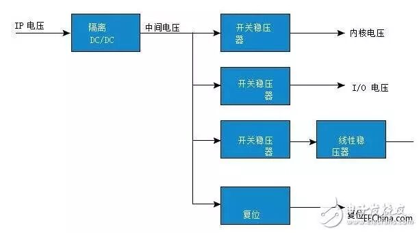
Figure 2 In this power architecture example, the output rails from the module require secondary regulation
We must carefully understand the behavior of the linear regulators used and the requirements for further filtering on the power lines. This requirement arises because devices like FPGAs and processors have switching frequencies that far exceed the levels that the control loops of linear regulators can handle. As noise frequency increases, the noise suppression capability of linear regulators decreases, necessitating additional filtering and decoupling techniques. Failure to understand this relationship can lead to issues with mixed-signal devices.
Another important consideration is the clock and reset architecture, especially in cases where multiple development boards need to be synchronized. At the architecture level, we must consider the clock distribution network: are we fan-outting a single oscillator across multiple development boards, or are we using multiple oscillators of the same frequency? To ensure robust reliability of clock distribution, we must consider: oscillator startup time. We must ensure that reset is activated throughout the time cycle (if needed).
Oscillator skew. If we are fan-outting an oscillator across multiple development boards, is timing critical? If so, we need to consider skew caused by traces on the card (due to connectors) and skew caused by the buffers themselves.
Oscillator jitter. If we are developing mixed-signal designs, we need to ensure that we use low-jitter clock sources, as increased jitter will reduce the signal-to-noise ratio of mixed-signal converters. The same applies when using gigabit-level serial links, as we need to use low-jitter clock sources to achieve good bit error rates on the link.
We must also pay attention to the reset architecture, ensuring that reset is only used where necessary. For example, SRAM-based FPGAs generally do not require reset.
If we are using asynchronous activation of reset, we need to ensure that its removal does not lead to metastability issues.
Clearly Defining Interfaces
Formal documentation of internal and external interfaces provides clear definitions at the mechanical, physical, and electrical levels for each interface, as well as protocols and control flows. This formal documentation is often referred to as Interface Control Documents (ICD). Of course, it is best to use standard communication interfaces whenever possible.
One of the most important aspects of interface definition is the “connectivity” of external interfaces. This process considers the pin assignments of the required connectors, the rated power of connector pins, the required number of insertions and removals, and any shielding requirements.
When considering connector types for our system, we should ensure that using the same type of connector in subsystems does not lead to adverse cross-connections. By using different types of connectors or adopting different connector keying (if supported), we can avoid the possibility of cross-connections.
Connectivity is one of the first aspects we address when determining the budget requirements established earlier. In particular, we can use crosstalk budgets to guide us in defining pin assignments. The example shown in Figure 3 illustrates the importance of this process. Rearranging pin assignments to layout ground reference voltage (GND) pins between signal 1 and signal 2 can reduce mutual inductance and the resulting crosstalk.
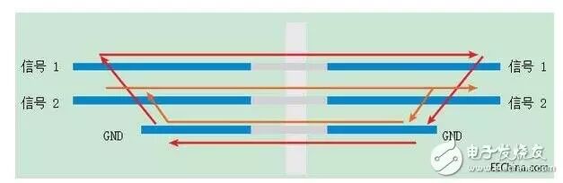
Figure 3 Connectivity is one of the most important features of interface definition
Interface Control Documents (ICD) must define the system grounding, especially when external EMC is required by the project. In this case, we must be careful to avoid allowing noisy signal grounds to radiate.
Engineers and project managers possess a range of strategies to ensure that the embedded systems they deliver meet quality, cost, and scheduling requirements. However, when projects encounter difficulties, we can be confident that, barring significant changes to the project, its past performance is a good indicator of its future performance.

1.Working for 10 years earns less than a new intern, because you haven’t done embedded!
2.Just writing code is not enough; the best programmers are those who can document!
3.Should you also try the “internet celebrity” development boards that foreign engineers are going crazy over?
4.In the battle between x86 and ARM, who will ultimately prevail?
5.Deep Learning – Eight Open Source Frameworks You Need to Know
6. How should we in technology “open our mouths” to eat this piece of VR cake?

Disclaimer: This article is a network reprint, and the copyright belongs to the original author. If there are any copyright issues, please contact us, and we will confirm copyright based on the copyright certificate you provide and pay remuneration or delete the content.