“RA MCU Testing Guide“PWM topic is here! In the previous article of the PWM series, we explored a core function that allows electronic signals to “flexibly vary”—an introduction to the output of PWM (Pulse Width Modulation). Renesas Embedded Encyclopedia will work with you to gradually implement PWM output based on the RA-Eco-RA4M2 development board, experiencing the charm of precise control through pulse width modulation, and see how this “magician of digital signals” plays a role in embedded development.
Open the Guide

2.2 PWM Output
The following functions are related to PWM output
-
R_GPT_Open() function: Initializes the timer module and applies the configuration;
-
R_GPT_Start() function: Starts the timer;
-
R_GPT_PeriodSet() function: Sets the frequency, frequency = clock source/period; if the frequency is set to 10K, then period = 100M/10K = 10000;
-
R_GPT_DutyCycleSet() function: Sets the duty cycle, duty cycle = cycle/period; if the duty cycle is set to 50%, then cycle = duty cycle * period = 50% * 10000 = 5000;
-
R_GPT_Reset() function: Resets the counter value to 0.
Finally, let’s take a look at the code:
Swipe left and right to view the full content
/*******************************************************************************************************************//** * main() is generated by the RA Configuration editor and is used to generate threads if an RTOS is used. This function * is called by main() when no RTOS is used. **********************************************************************************************************************/void hal_entry(void) { fsp_err_t err = FSP_SUCCESS; /* TODO: add your own code here */ SysTick_Init(); // Initialize system clock /* Initialize timer module. */ err = R_GPT_Open(&g_timer6_ctrl, &g_timer6_cfg); /* If initialization is successful, continue. */ assert(FSP_SUCCESS == err); /* Start the timer. */ err = R_GPT_Start(&g_timer6_ctrl); /* If initialization is successful, continue. */ assert(FSP_SUCCESS == err); while(1) { Delay_ms(500); R_IOPORT_PinWrite(&g_ioport_ctrl, GPIO_LED3, BSP_IO_LEVEL_LOW); R_IOPORT_PinWrite(&g_ioport_ctrl, GPIO_LED1, BSP_IO_LEVEL_HIGH); Delay_ms(500); R_IOPORT_PinWrite(&g_ioport_ctrl, GPIO_LED1, BSP_IO_LEVEL_LOW); R_IOPORT_PinWrite(&g_ioport_ctrl, GPIO_LED2, BSP_IO_LEVEL_HIGH); Delay_ms(500); R_IOPORT_PinWrite(&g_ioport_ctrl, GPIO_LED2, BSP_IO_LEVEL_LOW); R_IOPORT_PinWrite(&g_ioport_ctrl, GPIO_LED3, BSP_IO_LEVEL_HIGH); }#if BSP_TZ_SECURE_BUILD /* Enter non-secure code */ R_BSP_NonSecureEnter();#endifThe author only used the R_GPT_Open() and R_GPT_Start() functions, which are sufficient with the default frequency and duty cycle.
Most of the initialization work has been generated by software, making implementation relatively simple.
03
Experimental Phenomenon
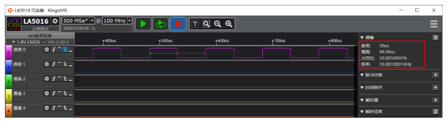
Next, let’s take a look at the #PWM output. The PWM signal can be observed through a #oscilloscope, and below the author used a logic analyzer to view the waveform.
The logic analyzer used by the author is the Kingst LA5016, but others can also be used. The relevant usage of the logic analyzer will not be introduced here; please refer to the official documentation.
First, connect the P600 pin to the logic analyzer’s CH0, then download the program to the board, open Kingst VIS, and start sampling.
Click to view the full image
Figure – PWM Output Implementation Phenomenon
From the above image, it can be seen that the actual measured frequency and duty cycle match the theoretical values.
This concludes the entire process of implementing PWM output based on the RA-Eco-RA4M2 development board. From the configuration of the GPT timer channels to the setting of duty cycle and frequency parameters, and finally to verifying the waveform accuracy with a logic analyzer, each step demonstrates the core value of PWM in precise control.
If you have new ideas regarding configuration parameters or code logic during practical operations, feel free to share and discuss in the comments section. The next issue of “RA MCU Testing Guide” will bring more practical function evaluations. Follow Renesas Embedded Encyclopedia to continue unlocking new skills in embedded development!
Renesas sample/development board application entry is as follows, you can scan the QR code or copy the link to the browser to obtain 👇
Application Entry
Renesas sample/development board application entry:
https://jsj.top/f/AgUyYV


Need Technical Support?
If you have any questions while using Renesas MCU/MPU products, you can scan the QR code below or copy the URL to the browser to open, and enter the Renesas Technical Forum to find answers or get online technical support.

https://community-ja.renesas.com/zh/forums-groups/mcu-mpu/
1
END
1
Recommended Reading

RA4M2 Development – Read HS3003 Data and Display on OLED, Serial Print (Part 2)

RA MCU Testing Guide | PWM Output with RA4M2 (Part 1)

Worried about OTA failure bricking your device? Boot swap can help you.