Principle
This project designs a water level control system based on a microcontroller, using the AT89C51 microcontroller as the core processor to design the minimum system, along with a digital display module, liquid level sensor, AD conversion circuit, relay circuit, water pump, and an independent button module. The system structure diagram is as follows::
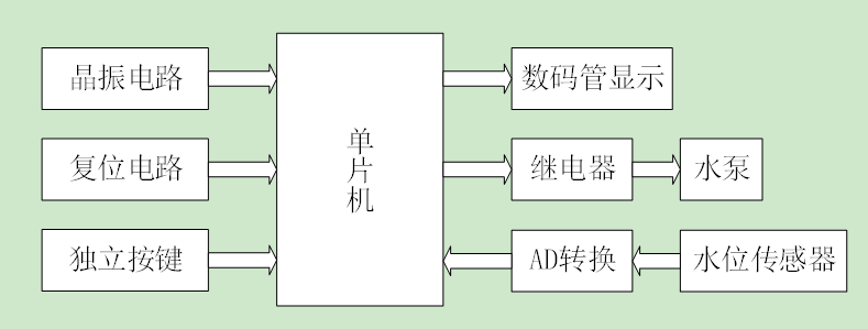
System Implementation Principle
The AT89C51 microcontroller has 32 programmable I/O ports, timers, external interrupts, and other resources that can connect many peripheral circuits. In this design, the liquid level sensor detects the water level information, which is converted to an electrical signal by the ADC0832 and then sent to the microcontroller for processing. Finally, the liquid level information is displayed on the digital display. The microcontroller compares the set upper and lower limits of the liquid level. When the level is below the lower limit, it controls the relay to activate the water pump to fill water, and when the level reaches the upper limit, it controls the relay to disconnect and stop filling. At the same time, a manual water filling function is implemented through an independent button.
Hardware Selection
AT89C51, ADC0832, buttons, digital display, relay, servo, LED, resistors, crystal oscillator
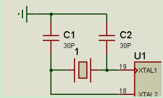
Crystal Oscillator Circuit
A crystal oscillator, also known as a crystal resonator, provides a reference clock signal for the microcontroller system. The internal resources of the microcontroller work based on the clock signal. Each peripheral circuit of the 51 microcontroller operates with a reference signal, which is the clock signal. The frequency of the microcontroller’s clock affects its operating speed, and the stability of the clock circuit directly impacts the stability of the microcontroller’s operation. The microcontroller can have both internal and external clocks; this design uses the internal clock of the microcontroller. The AT89C52 microcontroller’s pins 18 and 19 are the crystal oscillator pins. In this design, a 12M Hz crystal oscillator is chosen, with two capacitors to help stabilize the oscillation signal. The crystal oscillator circuit is shown below:
Liquid Level Sensor
The liquid level sensor (static pressure level gauge / level transmitter / level sensor / water level sensor) is a type of pressure sensor used to measure liquid levels. The static pressure submersible level transmitter (level gauge) operates based on the principle that the static pressure of the measured liquid is proportional to the height of the liquid. It uses an isolated silicon sensitive element or ceramic capacitor pressure-sensitive sensor to convert static pressure into an electrical signal, which is then temperature compensated and linearly corrected to convert into a standard electrical signal (generally 4~20mA/1~5VDC), suitable for various media level measurements in systems and industries such as petrochemicals, metallurgy, electricity, pharmaceuticals, water supply and drainage, and environmental protection. In the simulation of this design, a potentiometer is used to simulate the liquid level sensor.
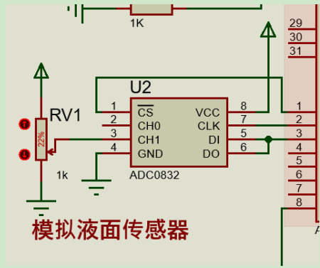
ADC0832
The ADC0832 is an 8-bit resolution, dual-channel A/D conversion chip produced by National Semiconductor. Due to its small size, compatibility, and cost-effectiveness, it is popular among microcontroller enthusiasts and enterprises, achieving a high level of penetration.
The ADC0832 is an 8-bit resolution A/D conversion chip, with a maximum resolution of 256 levels, suitable for general analog quantity conversion requirements. Its internal power input and reference voltage multiplexing allow the chip’s analog voltage input to be between 0~5V. The chip’s conversion time is only 32μS, featuring dual data output for data verification, reducing data errors, and providing fast and stable performance. The independent chip enable input makes it more convenient to connect multiple devices and control by the processor. Through the DI data input, it is easy to implement channel function selection. The circuit diagram is as follows:
Digital Display Module
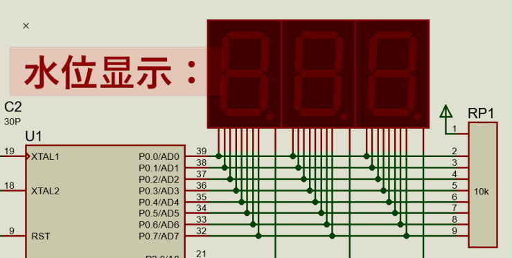
In this design, a 3-digit common cathode digital display is chosen to show the water level information. Common cathode display: refers to a digital display where all the LEDs’ cathodes are connected together to form a common cathode (COM). When using a common cathode display, the common terminal COM should be connected to ground (GND). When the anode of a certain segment is at a high level, the corresponding segment lights up; when the anode is at a low level, the corresponding segment does not light up. The digit selection terminal of the digital display is connected to the microcontroller’s P2 port, and the segment selection terminal is connected to the microcontroller’s P0 port. By applying a low level to the digit selection terminal, a certain digit of the digital display can be selected to light up, using dynamic scanning to light the display during programming. The digital display circuit is shown below.
Relay Circuit
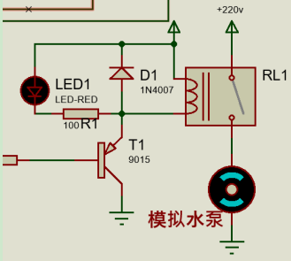
In this system design, the relay controls the water pump for filling. The relay part is controlled by a transistor. When the microcontroller’s IO port outputs a low level, the transistor conducts, the working indicator lights up, the relay operates, and the relay’s armature closes, thus activating the water pump circuit for filling. When the IO port outputs a high level, the transistor cuts off, the relay disconnects, and the water pump does not work. The circuit diagram is as follows.
Main Program Design
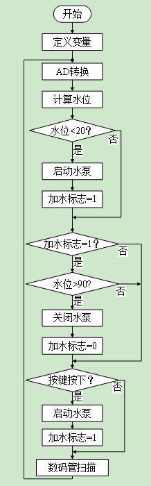
The main program’s task is to complete system initialization, acquire information from each module, and process it to control each module to perform the corresponding functions. The flowchart is as follows:
Digital Display Program Design
This design uses dynamic scanning to control the digital display. In the while loop, it continuously scans the digital display. The data to be displayed on the digital display is placed in an array, and when data is updated, only the values in the array need to be updated, and the program will display the values from the array on the digital display.
The digital display scanning code is as follows:
P0=0x00; //消隐 P2=0xfe; //选中第一位数码管 P0=table[water/100]; //百位 delayus(100); P0=0x00; //消隐 P2=0xfd; //选中第二位数码管 P0=table[(water%100)/10]; //十位 delayus(100); P0=0x00; //消隐 P2=0xfb; //选中第三位数码管 P0=table[water%10]; //个位 delayus(100);3.3 按键扫描程序设计按键扫描部分程序控制手动加水,在while循环中一致扫描按键端口,如果检测到端口为低电平,则表示按键按下,然后进行约10ms的消抖,再次检测按键是否按下,如果按键为按下状态,则表示按键确实按下。然后控制水泵加水。代码如下:if(!key) //扫描按键 { if(!keyflag) //判断按键状态 { delayus(1000); //延时消抖 if(!key) //再次扫描按键 { keyflag=1; //按键按下状态 if(water<90) //水位小于90开始加水 { motor=0; //启动水泵 flag=1; //表示在加水状态 } } } } else keyflag=0; //按键松开状态A/D Conversion Program Design
Using ADC0832 to convert the liquid level’s electrical signal into a digital quantity. When ADC0832 is not working, its CS input should be high, disabling the chip, while the levels of CLK and DO/DI can be arbitrary. When performing A/D conversion, the CS enable pin must be set to low and kept low until the conversion is fully completed. At this point, the chip starts conversion work, while the processor inputs clock pulses to the chip’s clock input pin CLK , and the DO/DI pin uses the DI pin to input the data signal for channel function selection. Before the first clock pulse goes low, the DI pin must be high, indicating a start signal. Before the second and third clock pulses go low, the DI pin should input two bits of data to select the channel function.The A/D conversion code is as follows:
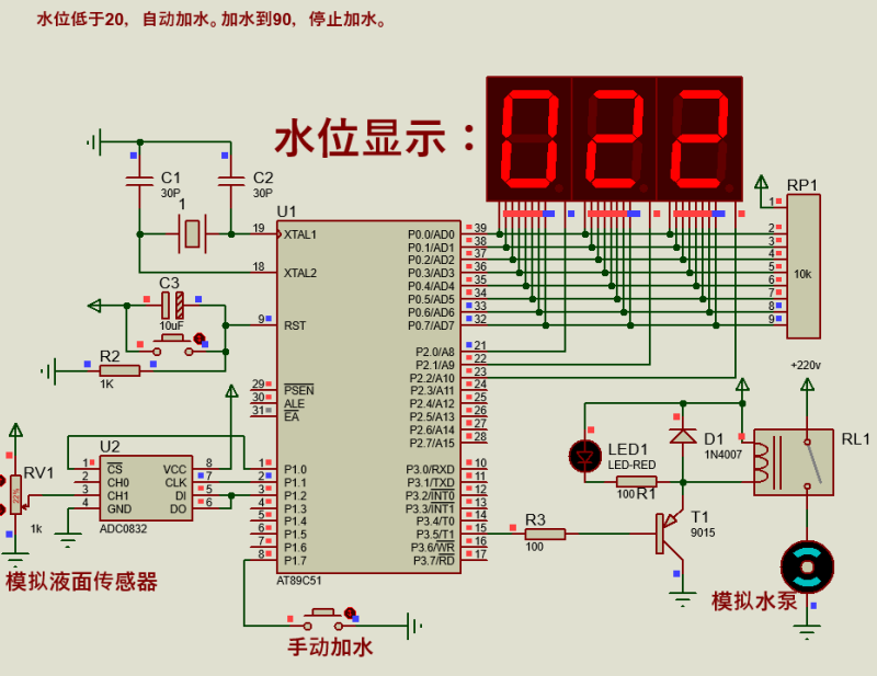
unsigned char ADC0832_Read(bit ch){ unsigned char i,dat; CS=1; //一个转换周期开始 CLK=0; //为第一个脉冲作准备 CS=0; //CS置0,片选有效 DIO=1; //DIO置1,规定的起始信号 CLK=1; //第一个脉冲 CLK=0; //第一个脉冲的下降沿,此前DIO必须是高电平 DIO=1; //DIO置1, 通道选择信号 CLK=1; //第二个脉冲,第2、3个脉冲下沉之前,DI必须跟别输入两位数据用于选择通道,这里选通道CH0 CLK=0; //第二个脉冲下降沿 DIO=ch; //ch为几,则选择通道几 CLK=1; //第三个脉冲 CLK=0; //第三个脉冲下降沿 DIO=1; //第三个脉冲下沉之后,输入端DIO失去作用,应置1 CLK=1; //第四个脉冲 for(i=0; i<8; i++)//高位在前 { CLK=1; //第四个脉冲 CLK=0; dat<<=1; //将下面储存的低位数据向右移 dat|=(unsigned char)DIO; //将输出数据DIO通过或运算储存在dat最低位 } CS=1; //片选无效 return dat; //将读出的数据返回}Simulation Diagram:
Simulation Result Analysis
After simulation testing, adjusting the potentiometer simulates changing the liquid level. When the level is below 20, the relay engages, the working indicator lights up, and the water pump starts filling. When the water level reaches 90, the relay disconnects, and the water pump stops. At the same time, when the water level is below 90, water can be manually filled using the button. Similarly, when the water level reaches 90, the relay disconnects, and the water pump stops. After multiple tests and analyses, the system has achieved all designed functions.
For customized Proteus simulation, search for: Amphibious Electronics. The method to obtain the above simulation program documentation can also be found, with various templates and customized simulation designs available: