Actual PLC programs are often extensions and combinations of certain typical small programs, so mastering some typical small programs is very beneficial for writing large and complex programs.In light of this, this article will provide some typical small programs for reference.
Start-Stop Circuit
The start-stop circuit is widely used in ladder diagrams, and its greatest feature is that it utilizes its own self-locking (also known as self-holding) to achieve a “memory” function. The circuit diagram is shown in Figure1. When the start button is pressed, the normally open contact X0 is closed, and without pressing the stop button (i.e., the normally closed contactX1 is ON), the coil Y0 is energized, and its normally open contact closes; when the start button is released, the normally open contact X0 is opened, at this time the “energy flow” through the normally open contact Y0 and the normally closed contact X1 continues to flow to the coil Y0,Y0 is still energized, which is the “self-locking” and “self-holding” function. When the stop button is pressed, its normally closed contact X1 opens, the coil Y0 is de-energized, and its normally open contact opens; when the stop button is released, the coil Y0 remains in a de-energized state.
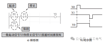
Figure1 Start-Stop Circuit
1) The condition for the “self-holding” function of the start-stop circuit is to connect the normally open contact of the output coil in parallel at both ends of the starting condition.
2) In practical applications, the start and stop signals may be composed of multiple contacts in series, as shown in the figure below; readers are encouraged to apply this flexibly.
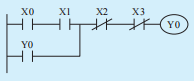
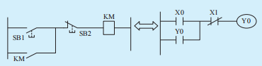
3) The start-stop circuit is derived from the single-phase continuous control circuit of a three-phase asynchronous motor. If you refer to the
single-phase continuous control circuit to understand the start-stop circuit, it will be extremely convenient. The derivation process (translation method) is as follows:
Set-Reset Circuit
Similar to the start-stop circuit, the set-reset circuit also has a “memory” function. The set-reset circuit is implemented by set and reset commands, and the circuit diagram is shown in Figure 2 .
Setting means writing a 1 to a certain bit, indicating there is output; resetting means writing a 0, indicating no output. They often depend on each other. Setting and resetting are often used together in programs. In most cases, once we perform a set operation somewhere in the program, we will inevitably need to perform a reset elsewhere. Their relationship is like a tacit waiting game; you wait for me to reset, I wait for you to set, mutually dependent. Next, we will detail how to use these operations.
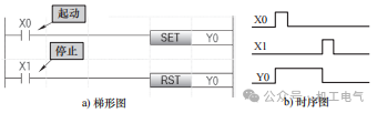
Figure 2 Set-Reset Circuit
When the start button is pressed, the normally open contactX0 closes, the set command is executed, the coilY0 is energized, and whenX0 opens, the coil Y0 continues to maintain the energized state; when the stop button is pressed, the normally open contactX1 closes, the reset command is executed, the coilY0 is de-energized, and whenX1 opens, the coilY0 continues to maintain the de-energized state.
Interlocking Circuit
In some cases, two or more relays cannot output simultaneously. To prevent them from outputting at the same time, their normally closed contacts are often connected in series in each other’s circuits; such a circuit is called an interlocking circuit. The circuit diagram is shown in Figure3 . When the forward start button is pressed, the normally open contactX0 closes, the coilY0 is energized and self-locking, its normally closed contactY0 opens, at this time even ifX1 is closed, the coilY1 will not actuate. When the reverse start button is pressed, the normally open contactX1 closes, the coil Y1 is energized and self-locking, its normally closed contactY1 opens, at this time even ifX0 is closed, the coilY0 will not actuate. When the stop button is pressed, the normally closed contactX2 opens, the coilsY0 and Y1 are both de-energized.
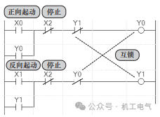
Figure3 Interlocking Circuit
1) Interlocking implementation: connect each other’s normally closed contacts in series in each other’s circuits.
2) Purpose of interlocking: to prevent two circuits from outputting simultaneously.
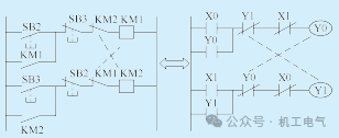
3) Similar to the understanding method of the start-stop circuit, the interlocking circuit can be understood through the forward and reverse circuit, as follows:
Delay Off Circuit
(1) Control Requirements
When the input signal is valid, there should be an immediate output signal; when the input signal is invalid, the output signal should stop after a delay.
(2) Solutions
Solution one is shown in Figure 4 .
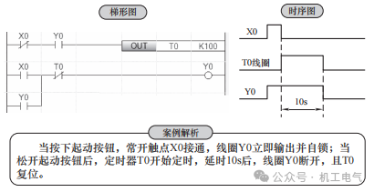
Figure 4 Delay Off Circuit Solution One
Solution two is shown in Figure 5 .
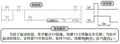
Figure 5 Delay Off Circuit Solution Two
Delay On/Off Circuit
(1) Control Requirements
When the input signal is valid, the output signal should be turned on after a delay; when the input signal is invalid, the output signal should be turned off after a delay.
(2) Solutions (see Figure 6)
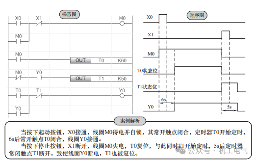
Figure 6 Delay On/Off Circuit
■ Long Delay Circuit
In the FX5U PLC, the maximum delay time of the timer is 3276.7s. If a longer delay time is needed, consider using multiple timers and counters in conjunction.
Long Delay Circuit Using Timers
The basic idea of this solution is to use multiple timers in series to achieve long delay control. When timers are used in series, the total timing is equal to the sum of the timing of each timer, that is, T=T0+T1, as shown in Figure 7 .
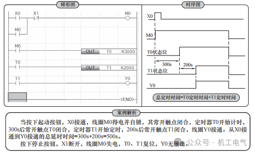
Figure 7 Long Delay Circuit Using Timers
Long Delay Circuit Using Counters
As long as a clock pulse signal is provided as the counting input signal for the counter, the counter can achieve timing functionality. The timing is equal to the product of the clock pulse signal period and the counter’s set value, that is, T=T1·Kc, where T1 is the clock pulse period, and Kc is the counter’s set value. The clock pulse can be generated by special auxiliary relays in the PLC, such as SM8013 (second pulse), SM8014 (minute pulse), or can be generated by a pulse generation circuit.
1) A long delay circuit containing one counter is shown in Figure 8 .
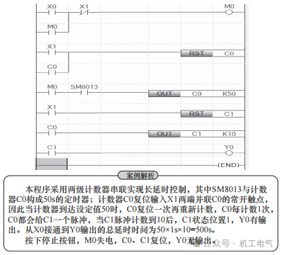
Figure 8 Long Delay Circuit Containing One Counter
2) A long delay circuit containing multiple counters is shown in Figure 9 .
Figure 9 Long Delay Circuit Containing Multiple Counters
Long Delay Circuit Using a Combination of Timers and Counters
The basic idea of this solution is to connect timers and counters to achieve long delay, essentially forming an equivalent multiplied timer, as shown in Figure 10 .
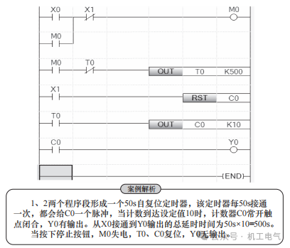
Figure 10 Long Delay Circuit Using a Combination of Timers and Counters
■ Pulse Generation Circuit
The pulse generation circuit is a widely used control circuit with many forms of construction, as follows:
Pulse Generation Circuit Composed of SM8013 and SM8014
The pulse generation circuit composed of SM8013 and SM8014 is the simplest. SM8013 and SM8014 are the most commonly used special auxiliary relays. SM8013 generates a second pulse, turning on for 0.5s and off for 0.5s; SM8014 generates a minute pulse, turning on for 30s and off for 30s. As shown in Figure11 .
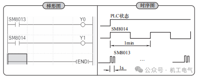
Figure11 Pulse Generation Circuit Composed of SM8013 and SM8014
Pulse Generation Circuit Composed of a Single Timer
Adjustable period pulse generation circuit, as shown in Figure12 .
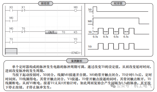
Figure12 Pulse Generation Circuit Composed of a Single Timer
Pulse Generation Circuit Composed of Multiple Timers
Pulse generation circuit composed of multiple timers, as shown in Figure13 .
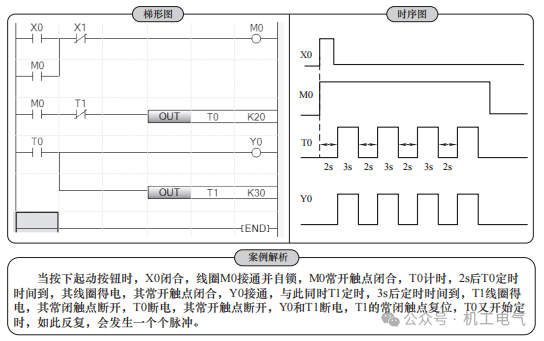
Figure13 Pulse Generation Circuit Composed of Multiple Timers
Sequential Pulse Generation Circuit
Three timer sequential pulse generation circuit as shown in Figure14 .
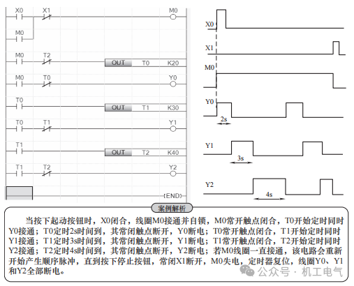
Figure14 Sequential Pulse Generation Circuit
Recommended Reading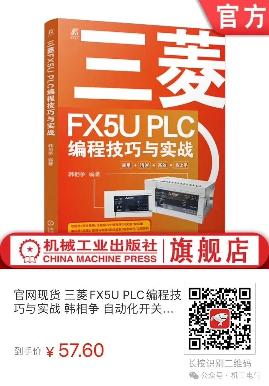
“Mitsubishi FX5U PLC Programming Skills and Practice” focuses on the Mitsubishi FX5U PLC, based on its hardware and instruction system and applications, emphasizing programming methods for switch control, analog control, positioning control, and high-speed counter speed measurement, with the design of control systems as the ultimate goal, progressing step by step from simple to complex. The book consists of 10 chapters, covering topics such as the composition and programming basics of the FX5U PLC hardware system, rapid application of FX5U PLC programming software, basic instructions and cases of FX5U PLC, application instructions and cases of FX5U PLC, design and cases of subroutines and interrupt programs, design of FX5U PLC switch control programs, design of FX5U PLC analog control programs, application cases of encoders and high-speed counters, design of FX5U PLC positioning control programs, comprehensive application cases of FX5U PLC, and terminal diagrams of FX5U PLC.
Source:“Mitsubishi FX5U PLC Programming Skills and Practice”
Typesetting: Wu Meiyi
Editor: Yang Qiong
Reviewer: Fu Chenggui