Common Causes and Solutions for PLC Failures During OperationPART1.Peripheral Circuit Component Failures
Such failures often occur after the PLC has been in operation for a certain period. If a component failure occurs in the PLC control circuit, the PLC control system will immediately stop working automatically.
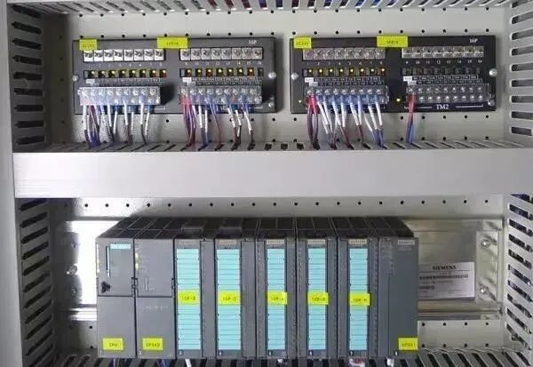
The input circuit is the port through which the PLC receives digital and analog input signals. The quality of its components, wiring methods, and their reliability are also important factors affecting the reliability of the control system.
For digital outputs, the PLC can have relay outputs, thyristor outputs, or transistor outputs. The specific type of output should be chosen based on the load requirements; improper selection can reduce system reliability and, in severe cases, prevent the system from functioning normally.
Additionally, the load capacity of the PLC’s output terminals is limited. If it exceeds the specified maximum limit, external relays or contactors must be used to ensure normal operation.
The quality of external relays, contactors, solenoids, and other actuating components is a significant factor affecting system reliability. Common failures include coil short circuits and mechanical failures that cause contacts to stick or not make proper contact.
PART2.Poor Terminal Wiring Connections
This type of failure tends to occur after the PLC has been in operation for a certain period, especially as the frequency of equipment operation increases. Due to wiring defects in the control cabinet or increased vibrations during use and mechanical wear, wiring terminals or component connection posts can become loose, leading to poor contact.
The method for troubleshooting this type of failure is to use a multimeter, aided by the control system schematic or the PLC logic ladder diagram for fault diagnosis and repair.
For certain important peripheral wiring terminals, to ensure reliable connections, soldering cold-pressed plates or cold-pressed pins are generally used.
PART3.Functional Failures Caused by Interference to the PLC
The various types of PLCs used in automation systems are specifically designed for industrial production environments. During the design and manufacturing process, multi-level anti-interference measures and selected components are employed, giving them strong adaptability to harsh industrial environments, operational stability, and high reliability. Therefore, they can generally be used directly in industrial environments without special measures.
Interference to the PLC can be categorized into internal and external interference. In actual production environments, external interference is random, unrelated to system structure, and the source of interference cannot be eliminated; it can only be limited based on specific situations.
Internal interference is related to system structure. It is mainly caused by the AC main circuit within the system, analog input signals, etc. By carefully designing system wiring or filtering through system software, internal interference can be minimized.
 PART4.Periodic PLC Crashes
The characteristic of periodic PLC crashes is that the PLC crashes or the program becomes disordered after running for a certain period, or different interrupt fault displays appear, but everything returns to normal after a restart. Based on practical experience, this phenomenon is most commonly caused by dust accumulation in the PLC body over time.
Therefore, the PLC chassis and slot interfaces should be regularly cleaned. During cleaning, compressed air or a soft brush can be used to blow away dust from the control board and various slots, and then 95% alcohol can be used to clean the slots and control board connectors. After cleaning, a careful inspection should be conducted, and normal operation can be restored upon rebooting.
Anti-Interference Technical Measures for PLCs in Production Sites
Typically, considerations are made from four aspects: power supply and grounding protection, wiring arrangements, shielding, and noise resistance.
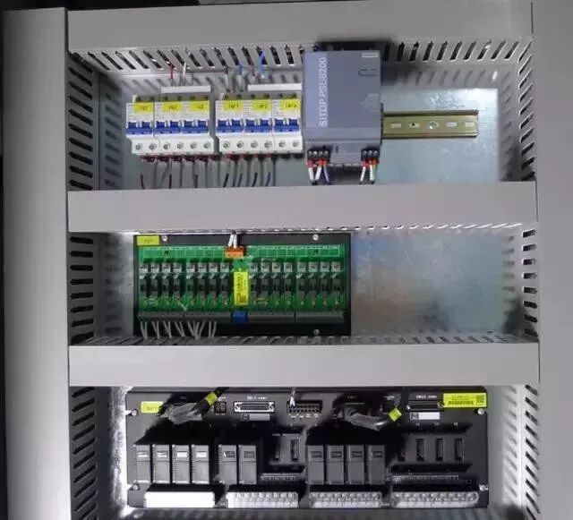
PART1.Power Supply and Grounding Protection
The anti-interference capability of the PLC itself is generally strong. Typically, the power supply for the PLC is wired separately from the power supply for the system’s power devices. The power supply lines have sufficient suppression capability against interference.
However, if power supply interference is particularly severe, a shielded isolation transformer can be added to reduce interference between the equipment and ground, thereby improving system reliability. If a system contains expansion units, their power supply must share a switch control with the basic unit, meaning they must be powered on and off simultaneously.
To suppress interference added to the power supply and input/output terminals, a dedicated ground wire should be connected to the PLC. The ground wire should be sufficiently thick, with a grounding resistance of less than 4Ω, and the grounding point should be as close to the PLC as possible, separated from other devices. For strong electrical devices in the power supply system, their metal components such as shells, cabinets, frames, bases, and operating handles must be grounded for protection.
The internal circuits of the PLC, including the CPU, memory, and other interfaces, should connect to a digital ground, while external circuits, including A/D and D/A, should connect to an analog ground, using thick short copper wires to star-connect the PLC baseplate to the central grounding point to prevent noise interference. When the PLC is not grounded, the installation bracket of the PLC should be capacitively grounded to suppress electromagnetic interference.
PART2.Wiring Arrangements
Wiring layout inside the electrical cabinet:
① Only shielded analog input signal lines can be placed in the same cable tray as digital signal lines; DC voltage digital signal lines and analog signal lines cannot be placed in the same cable tray as AC voltage lines.
② Only shielded 220V power lines can be placed in the same cable tray as signal lines.
③ The shielding of electrical cabinet cable connectors must be reliably grounded.
Wiring arrangements outside the electrical cabinet:
① Digital signal lines for DC and AC voltage must each use independent cables and should be shielded cables.
② Signal line cables can be placed in the same cable tray as power cables, but to improve noise resistance, a spacing of more than 10cm is recommended.
PART3.Shielding Treatment
The shielding of the PLC casing should generally ensure that it is floating with respect to the electrical cabinet. A level shielding plate (generally made of galvanized sheet) should be added to the bottom plate of the PLC casing, and a copper wire should be used to maintain a point connection with the bottom plate, with a cross-sectional area of not less than 10mm², to form a level shielding body that effectively eliminates external electromagnetic field interference.
For the shielding bus of analog signal lines, insulation can be used, and the central point should be connected to the reference potential or ground (GND). Grounding both ends of the digital signal line cable can effectively eliminate high-frequency interference.
PART4.Noise Resistance Measures
Parts located in strong magnetic fields (e.g., transformers) should be metal shielded. Fluorescent lighting should not be used for illumination inside the electrical control cabinet. The power supply for the PLC control system should also employ corresponding anti-interference measures.
Methods for anti-interference in the PLC control system power supply include using isolation transformers, low-pass filters, and applying spectral equalization methods. Among these, isolation transformers are the most commonly used, as the PLC’s I/O module power supply often uses DC24V, which must be stepped down through an isolation transformer and then rectified by a rectifier bridge, or directly supplied by a switching power supply.
PLC Fault Finding Flowchart
PLC program loss is usually caused by poor grounding, incorrect wiring, operational errors, and interference:
1. The PLC main unit and modules must have good grounding.
2. The phase and neutral wires of the main power supply line must be wired correctly.
3. Prepare a program package in advance for backup.
4. When using a handheld programmer to troubleshoot, the lock switch should be placed in the vertical position, and pulling it out can protect the memory.
5. If the PLC program is lost due to interference, the handling method can refer to the treatment of faults caused by interference.
··
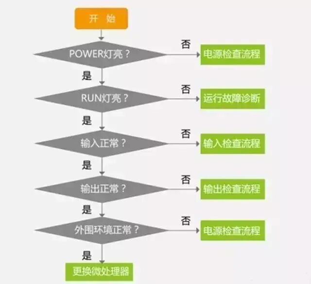
NO.1 Overall Inspection
According to the overall inspection flowchart, identify the general direction of the fault point and gradually refine it to find the specific fault, as shown in the figure below.
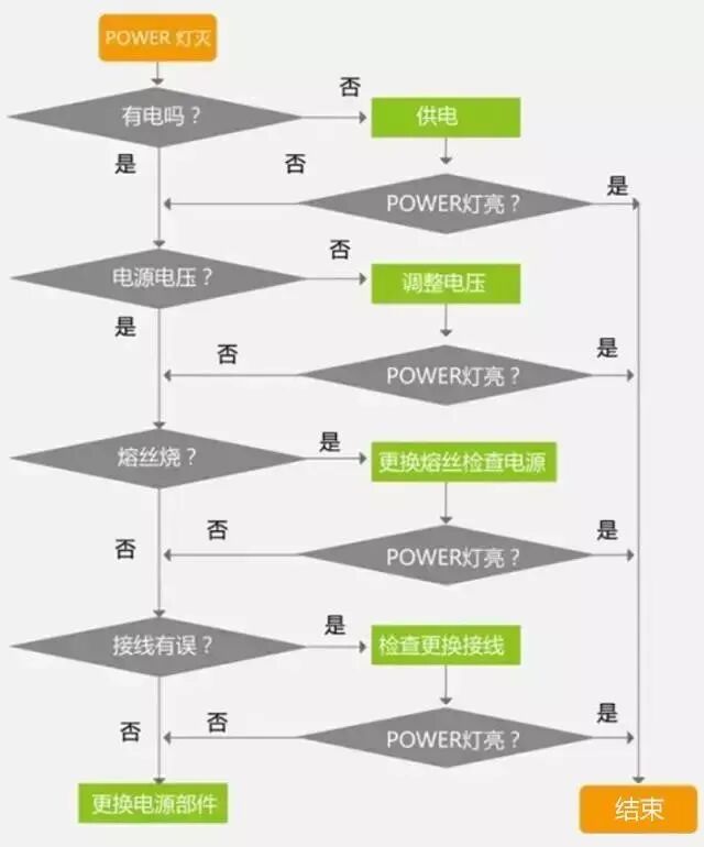
 ··NO.2 Power Supply Fault Inspection
If the power supply light is not on, the power supply system needs to be checked. The inspection flowchart is shown below.
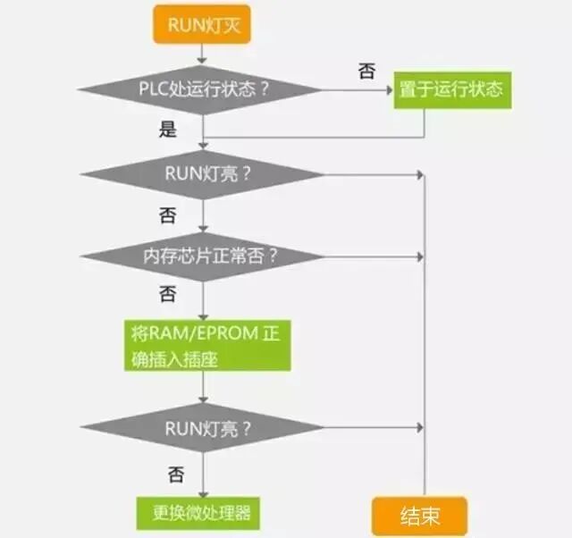
 ··NO.3 Operational Fault Inspection
If the power supply is normal but the operation indicator light is off, it indicates that the system has terminated normal operation due to some abnormality. The inspection flowchart is shown below.
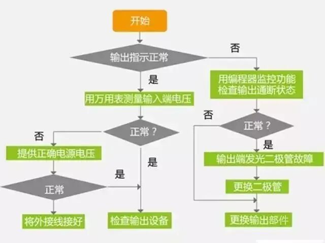
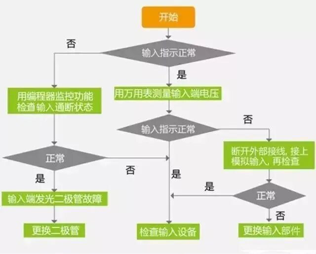
 ··NO.4 Input/Output Fault Inspection
The input/output is the channel through which the PLC communicates with external devices. Its normal operation is related not only to the input/output units but also to the status of connecting wires, terminals, fuses, and other components. The inspection flowchart is shown below.