ver0.2
Introduction
In previous articles, we introduced the services of the SCP and the working model of the SCP. From the perspective of SCP, all controlled objects are Agents, and the means of controlling each Agent mainly involves voltage, clock, etc., configured through the PPU. In this article, we will spend some time discussing the Power Control Framework (PCF). The purpose is twofold: first, to prepare for our later discussions on power domains and power modes at a system architecture level; second, to explore the topic of software transparency in power control, specifically how to achieve decoupling between upper-level software and the complex underlying power control. Before reading this article, we hope everyone will read our previous articles to grasp some basics and get a feel for the topic:
(1)[V-02] Basics of Virtualization – CPU Architecture (Based on AArch64)
(2)[A-03] ARMv8/ARMv9 – Multi-level Cache Architecture
(3)[A-21] ARMv8/v9 – Overview of SMMU System Architecture and Functions
(4)[A-25] ARMv8/v9 – System Architecture of GIC (Hardware Foundation of Interrupts)
(5)[A-38] ARMv8/v9 – Generic Timer System Architecture
(6)[A-41] ARMv9/v8 – Power Management System Architecture
(7)[A-42] ARMv9/v8 – Overview of SCP Service
Body
1.1 PCF Framework
Let’s first review how various Agents connect to the SCP under the ARM PCF framework, as shown in Figure 1-1.
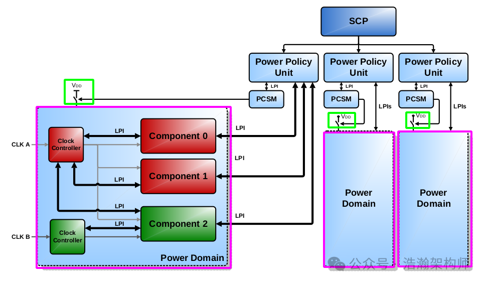
Figure 1-1 Power control framework overview
Let’s look at the description in the manual:
The power control framework (PCF) is a collection of standard infrastructure components, interfaces, and associated methods which can be used to build the infrastructure necessary for power management of a SoC.
The purpose of establishing the PCF standards is to connect the SCP with the components being power managed, forming the SOC power management system. This system not only specifies how to connect but also how to manage. Below, we will briefly introduce the core elements of Figure 1-1:
1.1.1 SCP & Component
The SCP and Component are easy to understand; the SCP is the brain that oversees POWER. It issues control commands, receives feedback from OSPM and system sensors, aggregates opinions from various sources, coordinates timing, and issues POWER control commands to the Component. The Component is essentially the Agent we discussed earlier, which are mostly independent functional modules on the SOC (CPU/GPU/APU, etc.).
1.1.2 Low-Power Interfaces (LPI)
In this section, we will look at how the various components of the PCF are connected:
The Low-Power Interfaces (LPI) are controller to device interfaces used to guarantee the availability, and removal, of a resource to the controlled component.
There are several LPIs (Q-Channel, P-Channel), each interface is complementary and should be selected as appropriate to the circumstances in which they are used.
The Q-Channel has simple run-stop semantics which are ideal for clock control and simple power control. The low-power mode entered can vary, but only according to a common configuration of both the component and the controller before the mode is requested.
The P-Channel has a mode specification capability meaning that transitions to different modes can be specified on a single interface. This makes it suitable for more complex power control with multiple modes and more complex mode transitions.
The Q-Channel looks like this:
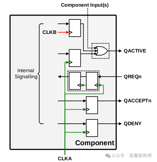
Figure 1-2 Q-Channel interface implementation
The P-Channel looks like this:
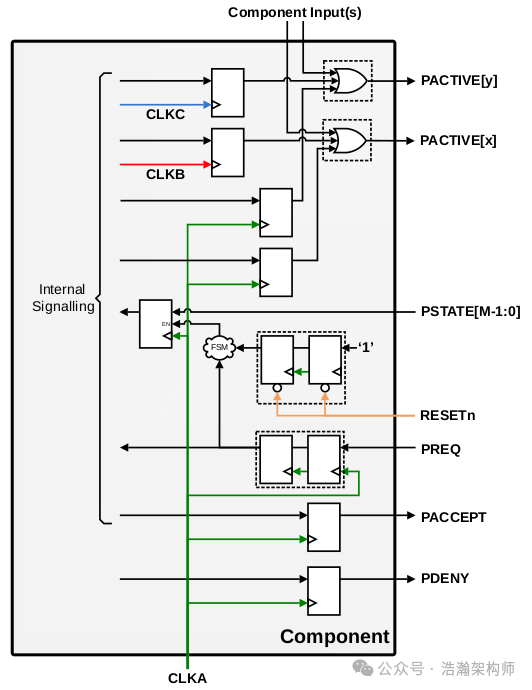
Figure 1-3 P-Channel interface implementation
Combining the manual’s description with Figures 1-2 and 1-3, we can summarize the Q-Channel and P-Channel (detailed discussions are beyond the scope of this article):
• Q-Channel and P-Channel are two hardware interface mechanisms used to facilitate communication between various nodes in the ARM power management system, primarily for dynamic voltage/frequency scaling (DVFS) and power state transitions.
• The Q-Channel circuit layout is relatively simple, primarily serving as a hardware-accelerated “emergency channel” that prioritizes handling power requests with high real-time requirements (low latency), such as rapid voltage and frequency switching.
• The P-Channel circuit layout is relatively complex, primarily serving as a flexibly configured “slow channel” that handles complex, time-consuming power operations, such as power state management and complex power state transitions (e.g., deep sleep, power domain switching). We will discuss power states and their management in more detail in future articles.
• The combination of the characteristics of Q-Channel and P-Channel ultimately enables rapid response and fine control in ARM’s power management scenarios.
1.1.3 Power Policy Unit (PPU)
With the LPI in place, the various Components of the power subsystem are physically connected at the system architecture level. The next step is to see how the SCP drives the operation of the entire system. As shown in Figure 1-1, the first subordinate that the SCP unites is the PPU.
The PPU is a standard component for abstracting software-controlled power domain policy down to low-level hardware control signaling. In a typical arrangement, one PPU is used to control each power-gated domain.
The SCP firmware can program the power policy of a PPU. This policy can be either a static power mode, or a range of modes that the PPU can transition between dynamically. This dynamic behavior is based on activity indicators from component LPIs without the need for further SCP programming. This enables hardware autonomous modes, such as dynamic retention, that can be entered and exited transparently to software. This provides responsive power control enabling components to be in the lowest power state possible, while maintaining functionality, with only policy level control from the SCP.
Combining the manual’s description, we can summarize as follows:
• The SCP controls the entire SOC’s power subsystem based on “Domain” as the basic unit through the PPU. With so many functional modules in the SOC needing to be driven by the Power subsystem, fine control naturally requires dividing them into different areas for management, with each area being governed by a PPU. The components within the area follow the PPU’s commands, while the PPU listens to the SCP, thus achieving the SCP’s goal of controlling the entire SOC power subsystem.
Figure 1-4 PPU integration example
• Another purpose of introducing the PPU is to achieve efficient power management. The PPU supports SCP’s programming management (as shown in Figure 1-5, which controls the internal registers of each PPU), thus achieving software-level transparency. The PPU executes the policies issued by the SCP decisively. For example, if the temperature rises, it can reduce frequency or shut down cores; if all PE-Cores within a Cluster go idle, the Cluster can also be transitioned to idle mode; upon receiving an event from the system, it can quickly wake up the sleeping IP, etc. This semi-autonomous design maximizes the subtle response of the hardware system, as no one wants their phone screen to take several seconds to transition from black to bright screen.
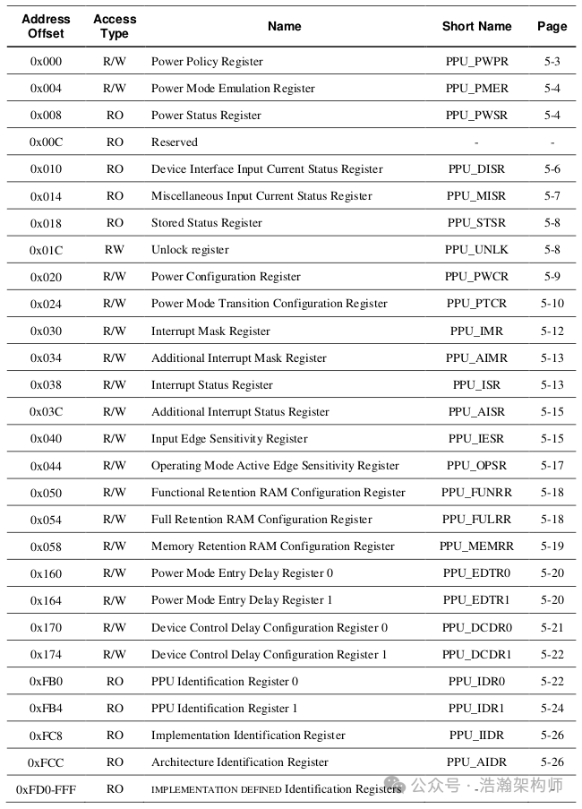
Figure 1-5 PPU register summary
• Through the standardized design of the PPU, it can more easily and quickly integrate more bus IPs, facilitating backward iteration of SOC platforms, as shown in Figure 1-6.
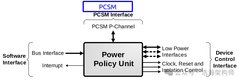
Figure 1-6 Power Policy Unit interfaces
Let’s look at the description of these interfaces in the manual:
The PPU interfaces are:
• Software Interface: A bus interface for programming, for example AMBA APB, and an interrupt that is used by the SCP for PPU configuration and policy control.
• Power Control State Machine (PCSM) Interface: An LPI to communicate power state changes to the PCSM that controls implementation and technology specific aspects of power control such as power switch and memory retention control.
• Device Control Interface: Low-level control for components within the power domain. It includes:
– One or more LPI, depending on the needs of the components in the power domain.
– Device controls, including clock enables, resets, and isolation controls.
Here, we will focus on the PCSM:
Power Control State Machine (PCSM)
Low-level power control details such as power switch control or control signals for logic or RAM retention can be technology and cell library specific. To avoid modification of the core PPU function, it interfaces to an implementation dependent power control state machine (PCSM) that controls these elements. This allows the PPU to be a generic and reusable standard component.
The power control state machine is controlled from the PPU with a P-Channel LPI interface. The PCSM converts the P-Channel power mode requests to implementation dependent controls.
The PCSM connects to the PPU through the P-Channel, which is more suitable for handling complex tasks. The most important job of the PCSM is to coordinate the power state transitions of various components controlled by the PPU (as shown in Figure 1-7), ensuring that all components are synchronized, thus enhancing the robustness of the entire system. For example, the timing for entering a low-power state involves adjusting voltage first, then clock, and finally adjusting the states of each Component, completing the power state adjustment within the domain. (We will discuss power states in detail in future articles, so we will not elaborate here.)
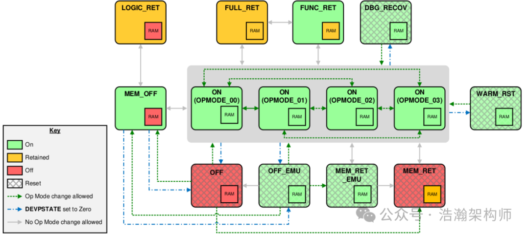
Figure 1-7 Power mode transitions
1.1.4 Clock Controller
Another important component of the PCF framework is the clock control unit.
The PPU provides clock gating controls for the power domain. This ensures that clock inputs can be gated as required to maintain safe and correct behavior when entering and exiting power modes.
The PPU provides multiple clock enables for use in different power modes. For example, when the off state of a power domain is emulated for debug purposes. In this case, certain clocks need to remain enabled to allow debug access to the component.
The clock control unit also provides standardized interfaces, facilitating the connection of upstream and downstream power control hardware units, as shown in Figure 1-8.
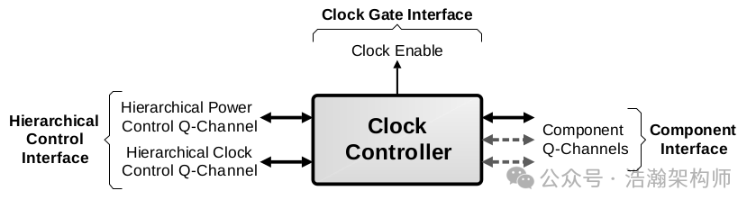
Figure 1-8 Clock controller interfaces
Let’s look at the description of the Clock Controller in the manual:
The clock controller interfaces are:
• Clock Gate Interface: This is a clock enable signal to control a clock gate.
• Component Interface: Consisting of one or more Q-Channel interfaces, depending on the needs of the domain.
• Hierarchical Control Interface: This consists of a power control and clock control hierarchical Q-Channels to allow control over the clock controller from higher-level components.
The clock controller combines clock control LPIs from multiple components to manage a single clock domain. It uses the LPIs to ensure all components are in a quiescent state before the clock is gated. It also ensures the clock is running again before any component leaves the quiescent state.
In ARM architecture power management, the Clock Controller is a key hardware module responsible for generating, distributing, and managing clock signals within the SoC, directly affecting processor performance, power consumption, and peripheral operational states. It can be said to be the most important lever for the SCP to control the entire system’s power. The clock is the heart of the entire SOC operation; controlling the pulse of the heart firmly controls the entire system. Typical scenarios include DVFS dynamic control of IP working frequency; or during power state transitions, shutting down the CPU clock while maintaining voltage in shallow sleep mode for quick wake-up; or completely shutting down clocks and power in deep sleep state. All these rely on the configuration and state storage and recovery of the clock controller. The implementation of the Clock Controller is not limited to the form shown in Figure 1-1; it can also implement cross-domain system architectures as shown in Figure 1-9.
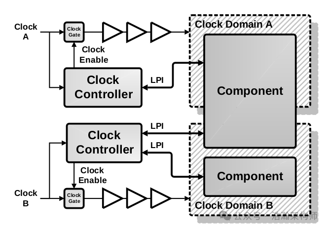
Figure 1-9 Clock gating a component with multiple clock domains
1.2 Power Control Software Transparency
In the previous section, we discussed the core components of the PCF framework. The complete PCF system includes more than just those nodes, but we will not elaborate here, as we are still preparing for the discussion on OSPM. There is no need to delve into overly detailed hardware implementation details; interested readers can refer to the relevant literature in the appendix. Here, we will discuss the topic of software transparency in power control within the PCF, which ultimately serves the PCSA system, as shown in Figure 1-10:
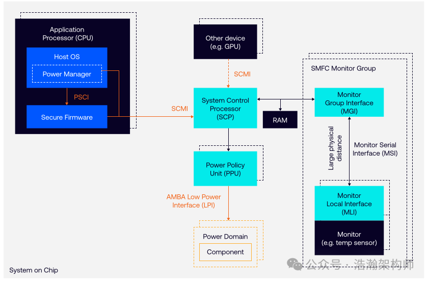
Figure 1-10 PCSA main components
Let’s look at the description in the manual:
The Arm architecture is designed to be highly energy efficient. However, simply using individually power-efficient components is not sufficient for best results. Minimizing system power requires intricate and coordinated clock, power, and thermal management.
The Power Control System Architecture (PSCA) (DEN0050) defines a flexible framework for system power control integration using standard infrastructure components and low-power interfaces.
It enables a generic OS to delegate SoC-specific power and performance control to a specialized subsystem, while allowing the OS to remain responsible for assessing the performance needs of workloads and translating them to desired performance levels.
The PSCA is important in most markets, including mobile and servers, and is implemented in many Arm Compute Systems (CSS).
The key elements of the PCSA are as follows:
• System Control Processor (SCP). A processor, for example a microcontroller, which offloads and abstracts details away from the host Operating System Power Manager (OSPM).
◦ The SCP operates independently from, and reacts faster than the OS kernel. It securely arbitrates power requests from multiple sources, including when the main application processors are themselves in a low-power state or subject to thermal throttling.
◦ A complex system may use additional, distributed secondary SCPs to provide functional encapsulation of subsystems and lower-latency local control. Product documentation refers to these as Local Control Processors (LCPs).
• Power Policy Unit (PPU). Hardware which converts power domain policy to basic power control signals (AMBA Low Power Interface) for each power domain.
• System Monitoring Control Framework (SMCF). Defines how data from distributed sensors can be collected and trigger alerts in the SCP, for example when a temperature threshold is breached. The SMCF is designed to manage a large and diverse set of on-chip sensors. It does this by presenting software with a standard interface to control the monitors, regardless of type, and reducing the software load of sampling and data collection.
This transparent implementation approach can also be understood as developing according to the specifications of the PCSA system to maximize the decoupling of Power Control hardware and software development from the Host OS. Specifically, the design purpose of the PCSA system is to allow Agents on various power control subsystems (generally the OSPM running on the CPU) to avoid getting bogged down in the complex work of coordinating the registers and timing of each controlled node (SCP, PPU, PCSM, Clock Controller, etc.), focusing instead on policies and simple configurations. This also requires standardization of the hardware design and integration of the power subsystem, including interface standardization between each other, control logic, and timing transmission standardization, which is also the original intention of the PCF (Power Control Framework) design.
In future articles discussing the Power software architecture, we will also cover ARM system architecture content. In fact, not only the power subsystem but all subsystems should achieve decoupled development to realize the fastest and most efficient iteration of products based on the ARM architecture. We will not elaborate on this here, mainly to help everyone establish a concept and understand the basic environment on which the concept of domains in power management relies.
Conclusion
In this article, we provided a brief introduction to the power control framework PCF and discussed some core components such as PPU, PCSM, and Clock Controller. Throughout this process, two important concepts were introduced: one is the concept of domains in power management, and the other is the concept of power modes. The introduction of the domain concept aims to make the granularity of power management more refined, while the introduction of power modes aims to coordinate the working rhythm of power management. Finally, we explored how the PCF hides the complex control logic of power management to achieve transparency for upper-level software. That’s all for today; please follow, comment, and share. Thank you all.
Postscript
Recently, while conducting deep optimization of the system, I found that in the end, programmers may have to compete with hardware. Any deep optimization of a software subsystem (especially in virtualization architecture) must be based on a correct understanding of hardware. Understanding how hardware works helps us gain a deeper understanding of software architecture and some designs in the kernel, which in turn allows us to understand the bottlenecks in the system more profoundly, leading to optimization proposals that are more practical and effective. For example, if the efficiency of entering or exiting STR is low, analyzing the bottlenecks of such issues requires a broader perspective and a deep understanding of micro principles. At the very least, you need to know what documents to request from chip manufacturers (laughs).
References
[01] <DEN0050D_Power_Control_System_Architecture.pdf>
[02] <armv8_a_power_management_100960_0100_en.pdf>
[03] <Power_Policy_Unit_Architecture_Specification.pdf>
[04] <DEN0024A_v8_architecture_PG.pdf>
[05] <79-LX-LD-s003-Linux设备驱动开发详解4_0内核-3rd.pdf>
[06] <80-PGxxx-35_QNX_Thermal_Manager_Overview.pdf>
[07] <80-pgxxx-7_n_qnx_power_management_software_architecture_ref.pdf>
[08] <80-ARM-POWER-HK0001_一文搞懂ARM_SoC功耗控制架构.pdf>
[09] <Arm_Power_and_Performance_Management_SCMI_White_Paper.pdf>
[10] <80-ARM-POWER-cs0001_Arm-SoC-power功耗控制架构.pdf>
[11] <80-LX-LK-cl0009_深入理解Linux电源管理.pdf>
[12] <DEN0056D_System_Control_and_Management_Interface_v3_1.pdf>
[13] <arm_total_compute_2021_reference_design_software_developer_guide_en.pdf>
[14] <arm_total_compute_2022_reference_design_software_developer_guide_en.pdf>
[15] <arm_cortex_m85_processor_trm_en.pdf>
[16] <DEN0108_00eac0_smcf-archl-SMCF-Architecture-Specn.pdf>
[17] <DEN0022F.b_Power_State_Coordination_Interface.pdf>
[18] <MTxxxx_SCP_User_Manual_V1.0.pdf>
[19] <learn_the_architecture_arm_system_architectures_en.pdf>
Glossary
AP – application processor
OSPM – Operating System Power Management
WFI – Wait For Interrupt
WFE – Wait For Event
DVFS – Dynamic Voltage and Frequency Scaling
SCU – Snoop Control Unit
OPP – Operating Performance Point
PSCI – Power State Coordination Interface
PPU – Power Policy Unit
PCSA – Power Control System Architecture
SoC – System-on-Chip
PCF – Power Control Framework
SCP – System Control Processor
BSP – board support package
SCMI – System Control and Management Interface
EAS – Energy Aware Scheduling
IPA – Intelligent Power Allocation
ACPI – Advanced Configuration and Power Interface
LPI – Low-Power Idle
CPPC – Collaborative Processor Performance Control
PCSM – power control state machine
AOSS – Always-on subsystem
PMIC – Power Management Integrated Circuit
JM – job manager
AON – always on domain
SBSA – Server Base System Architecture
CLK_CTRL – Clock Controller
LPD – Low Power Distributor
LPC – Low Power Combiner
P2Q – P-Channel to Q-Channel Convertor