Li Dongxia, Meng Long, Wang Lei, Li Haoyang, Liu Haitao(Civil Aviation University of China, School of Electronic Information and Automation, Tianjin 300300)Abstract: To address the lack of a real verification platform for the DME signal interference suppression algorithm in the L-band digital aeronautical communication system receiver, a prototype system of L-DACS1 is built using software-defined radio technology. Based on the technical parameters and superframe structure of the L-DACS1 system’s forward link, a prototype transmitter and receiver for the L-DACS1 system’s forward link are designed and implemented using Yun SDR320 and Matlab, enabling signal transmission and reception in a real wireless channel environment. Test results indicate that the designed L-DACS1 system’s forward link platform meets system specifications and operates stably, providing a verification platform for future DME interference suppression algorithms.Keywords: L-DACS1 system; forward link; Yun SDR320; DME; signal transceiver; wireless channelClassification number: TN859-34 Document identification code:AArticle number: 1004-373X (2022) 03-0023-05
0 Introduction
To ensure the safe, reliable, and efficient operation of civil aircraft and to enhance airspace capacity, the International Civil Aviation Organization (ICAO) has established the L-band Digital Aeronautical Communication System (L-DACS) as one of the primary technical means for future aeronautical mobile communication [1]. Currently, there are two candidate technical solutions for L-DACS: one is the L-DACS1 based on multi-carrier modulation technology [2]; the other is the L-DACS2 based on single-carrier Gaussian minimum shift keying [3]. L-DACS1 has attracted widespread attention from the aviation manufacturing industry and academia due to its advantages of large transmission capacity, strong multipath resistance, and high spectral efficiency [4]. Since the operating spectrum of the L-DACS1 system partially overlaps with that of the existing DME (Distance Measuring Equipment) system [5], DME signals inevitably interfere with the L-DACS1 system receiver.
Currently, many algorithms have been proposed both domestically and internationally to suppress DME signal interference in L-DACS1 system receivers, such as pulse blanking and pulse clipping interference suppression algorithms [6], compressed sensing signal reconstruction interference suppression algorithms [7], and decision feedback pulse noise estimation interference suppression algorithms [8]. The research on these interference suppression algorithms mainly combines theoretical analysis with simulation, without constructing a real test platform to verify their effectiveness. To further study the impact of DME signals on the performance of the L-DACS1 system receiver, this paper designs and implements the transmitter and receiver of the L-DACS1 system’s forward link based on the Yun SDR320 platform and Matlab software platform according to the specifications of the L-DACS1 system [2]. The transmitter generates transmission signals, which are received by the receiver after passing through a real wireless channel. This platform can verify the performance of the L-DACS1 system transmitter and receiver and provide a real environmental platform for further verification and comparison of different DME interference suppression algorithms.
1 Yun SDR Software-Defined Radio Platform
Software-defined radio refers to the configuration of physical hardware through software programming to achieve various radio functions without changing hardware conditions [9]. By using software-defined radio technology, various functions of communication system links are realized through a software platform, including signal generation, modulation and demodulation, encoding and decoding, filtering, etc.
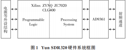
The Yun SDR320 experimental platform developed by Beijing Weishi Rui Technology Co., Ltd. is a portable software-defined radio platform specifically designed for wireless communication system research. The Yun SDR320 interacts with the PC via a Gigabit Ethernet cable and is widely used due to its wider frequency range and analog bandwidth. The basic hardware structure of the Yun SDR320 experimental platform consists of three parts: ZYNQ embedded processor, AD9361 [10] RF front end, and power supply circuit. The embedded processor uses the Xilinx ZYNQ ZC7Z020 CLG400 model SoC chip to complete the digital baseband signal processing of the signal source. The RF front end uses ADI’s AD9361 chip to implement functions such as digital signal processing, digital up/down conversion, digital/analog and analog/digital conversion, filtering, and RF transceiving. The hardware system block diagram of the Yun SDR320 is shown in Figure 1.
2 L-DACS1 System Forward Link Physical Layer Transmission Characteristics
L-DACS1 is an aviation mobile communication system based on Orthogonal Frequency Division Multiplexing (OFDM) multi-carrier transmission technology, adopting Frequency-Division Duplex (FDD) communication mode [2]. The forward link of the system adopts OFDM transmission technology, where the basic data transmission unit is a superframe, with a working frequency band of 985.5~1085.5 MHz and a bit transmission rate of 303~1373 Kb/s.
2.1 L-DACS1 System Forward Link Physical Layer Technical Parameters
The main technical parameters of the L-DACS1 system physical layer are shown in Table 1.
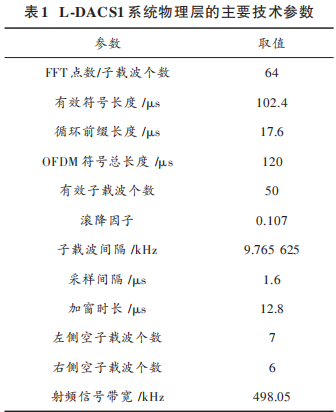
The total number of subcarriers in the L-DACS1 system forward link OFDM system is 64, including 50 effective subcarriers, 14 DC subcarriers, and null subcarriers, with a subcarrier spacing of 9.765625 kHz and an RF channel bandwidth of 498.05 kHz. The total length of the OFDM symbol is 120 μs, where the effective symbol length is 102.4 μs, and the cyclic prefix length is 17.6 μs.
2.2 L-DACS1 System Forward Link Frame Structure
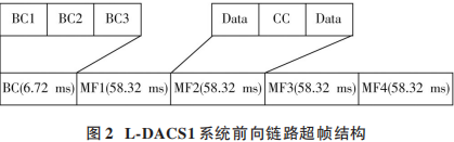
The superframe structure of the L-DACS1 system forward link is shown in Figure 2. Each superframe consists of 1 broadcast (BC) frame and 4 multiframes (MF). The broadcast frame is used to transmit broadcast information for the forward link, while the multiframes are used to carry higher-layer modulation symbols. Each broadcast frame lasts for 6.72 ms and consists of 3 subframes: BC1, BC2, and BC3. BC1 and BC3 subframes are identical and last for 1.8 ms, while the BC2 subframe lasts for 3.12 ms. Each multiframe lasts for 58.32 ms and consists of 9 variable-length Data/CC subframes, each lasting 6.48 ms. Each superframe lasts for 240 ms, capable of transmitting a total of 2000 OFDM symbols.
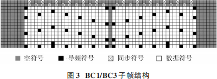
The structure of the BC1/BC3 subframe is shown in Figure 3. Each subframe consists of three parts: synchronization symbols, data symbols, and pilot symbols. The synchronization symbols are used for the receiver to establish superframe synchronization and accurately locate the starting position of the frame header; the data symbols carry higher-layer bit information; and the pilot symbols are used for channel estimation by the receiver.
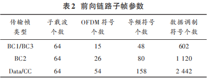
The structures of BC2 and Data/CC subframes are similar to those of BC1/BC3, with their parameters shown in Table 2.
3 System Design and Implementation
3.1 System Platform Structure Design
The forward link communication platform of the L-DACS1 system mainly includes two parts: the PC side and the Yun SDR320 device, as shown in Figure 4.

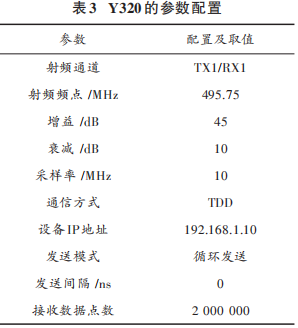
At the transmitter end, the digital baseband signal generated by the sending PC is sent through a Gigabit Ethernet cable to the DSP processor for digital modulation. The signal is then converted to an intermediate frequency signal by the digital upconverter, followed by analog signal conversion through a digital-to-analog converter. The analog signal is amplified to sufficient power by the RF section and transmitted into the wireless channel via an antenna. At the receiver end, the radio signal received by the antenna is amplified and converted to a digital signal through analog-to-digital conversion. The digitized signal is then converted from intermediate frequency to baseband by the digital downconverter, and the baseband signal is sent to the DSP processor for digital demodulation. The demodulated signal is sent through a Gigabit Ethernet cable to the receiving PC to recover the original transmitted sequence. The parameter configuration of the Y320 is shown in Table 3.
3.2 Implementation of the Transmitter
The forward link transmitter of the L-DACS1 system mainly consists of encoding interleaving, modulation, frame mapping, and window shaping. The implementation block diagram is shown in Figure 5.

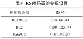
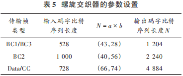
To randomize the transmitted bit sequence, the bit sequence generated by the source first undergoes bit scrambling processing; an appropriate coding method is selected, where the outer coding adopts RS coding with parameters set as shown in Table 4, and the inner coding adopts (171, 133, 7) convolutional code. After that, according to the type of transmission frame, an appropriate interleaving method is selected. The interleaving method for the broadcast (BC) frame is spiral interleaving, while the interleaving method for the Data/CC frame is block interleaving and spiral interleaving, with parameters set as shown in Table 5.
The bit sequence after encoding and interleaving is modulated into symbols. The modulated symbol sequence is mapped with the generated pilot sequence and synchronization sequence to the BC1, BC2, BC3 subframes, and Data/CC subframe. According to the L-DACS1 system forward link superframe structure, the subframes are combined into a superframe, and the superframe is modulated into OFDM symbols through IFFT. Finally, a cyclic prefix (CP) is inserted, time-domain window processing is performed, and parallel data is converted to serial data for transmission to the Y320 via Gigabit Ethernet. This completes the design of the transmitter part of the L-DACS1 system forward link.
3.3 Implementation of the Receiver
The forward link receiver of the L-DACS1 system mainly consists of synchronization, channel estimation, channel equalization, and demodulation decoding. The implementation block diagram is shown in Figure 6.
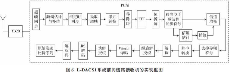
The signal received by the Y320 is transmitted to the PC side via Gigabit Ethernet. The received signal is first used to determine the approximate starting position of the superframe header based on the specific structure of the broadcast (BC) frame, establishing superframe synchronization. Then, the carrier frequency offset of the received signal is obtained using the synchronization symbols of each data frame in the forward link, and compensation is performed. Afterward, fine timing synchronization is achieved using the synchronization symbols to accurately determine the starting position of the superframe header. A complete superframe is extracted from the received data, serial-to-parallel conversion is performed, the CP is removed, and OFDM demodulation is completed using FFT. The superframe is then disassembled, extracting the BC1, BC2, BC3 subframes, and Data/CC subframes. The null subcarriers and DC subcarriers are removed from the subframes, and the pilot symbols in the subframes are used for channel estimation, followed by one-dimensional linear interpolation based on the channel estimation values of each subchannel for channel equalization. The data after channel equalization has the pilot symbols removed and is converted from parallel to serial. Depending on the type of transmission frame, the obtained serial data undergoes demodulation, deinterleaving, and decoding, with the deinterleaving and decoding parameters consistent with those of the transmitter. Finally, the original transmitted bit sequence is recovered after descrambling. This completes the design of the receiver part of the L-DACS1 system forward link.
4 Testing and Analysis
To test the correctness of the L-DACS1 system forward link transmitter and receiver design based on Y320, this paper observes the transmitter superframe power spectrum, receiver received signal power spectrum, and the convergence degree of the subframe constellation.
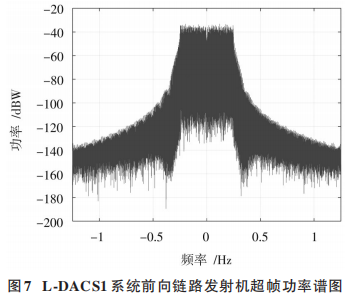
The superframe power spectrum of the L-DACS1 system forward link transmitter is shown in Figure 7. From the transmitter power spectrum, it can be observed that the RF signal bandwidth of the L-DACS1 system forward link is close to 0.5 MHz, with DC at zero frequency, transmitting no information. The test results are consistent with the standards of the L-DACS1 system forward link transmitter.
The superframe power spectrum of the L-DACS1 system forward link receiver is shown in Figure 8.
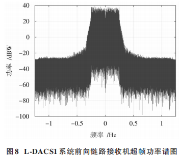
From the receiver power spectrum, it can be observed that the bandwidth of the received signal power spectrum is also close to 0.5 MHz, with DC at zero frequency, proving that the receiver successfully received the modulated signal sent by the transmitter in the air.
In the case of QPSK modulation used in the L-DACS1 system forward link transmitter, the constellation after channel estimation and equalization using the pilot symbols in the subframes is shown in Figure 9.
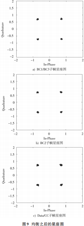
Among them, Figure 9a) is the constellation after equalization of the BC1/BC3 subframe; Figure 9b) is the constellation after equalization of the BC2 subframe; Figure 9c) is the constellation after equalization of the Data/CC subframe.
From the constellation after equalization, it can be observed that the constellation points of the BC1, BC2, BC3, and Data/CC subframes converge well, meeting design requirements.
5 ConclusionThis paper designs and implements the transmitter and receiver of the L-DACS1 system’s forward link based on the technical parameters and superframe structure specified by the L-DACS1 system protocol, using the software-defined radio Y320 and Matlab. Joint debugging tests of the transmitter and receiver were conducted. Through testing the power spectra of the transmitter and receiver and observing the convergence of the constellation diagrams, it can be confirmed that the designed L-DACS1 system platform operates effectively, and this platform will serve as a practical verification platform for subsequent algorithm research.References[1] NAJETT N, DE LACERDA R, AZOULAY A, et al. Survey on the future aeronautical communication system and its development for continental communications [J]. IEEE transactions on vehicular technology, 2013, 62(1): 182-191.[2] SAJATOVIC M, HAINDL B, EHAMMER M, et al. L-DACS1 system definition proposal: deliverable D2 [M]. Brussels, Belgium: EUROCONTROL, 2009.[3] FISTAS N. L-DACS2: system definition proposal: deliverable D2 [M]. Brussels, Belgium: EUROCONTROL, 2009.[4] BRANDES S, EPPLE U, GLIGOREVIC S, et al. Physical layer specification of the L-band digital aeronautical communication system (L-DACS1) [C]// Integrated Communications, Navigation & Surveillance Conference. Crystal City, VA, USA: IEEE, 2009: 1-12.[5] EPPLE U, SCHNELL M. Overview of legacy systems in L-band and its influence on the future aeronautical communication system LDACS1 [J]. Aerospace & electronic systems magazine, 2014, 29(2): 31-37.[6] EPPLE U, SCHNELL M. Overview of interference situation and mitigation techniques for LDACS1 [C]// 2011 IEEE /AIAA Digital Avionics Systems Conference. Seattle, WA, USA: IEEE, 2011: 1-12.[7] Liu Haitao, Zhang Zhimei, Cheng Wei, et al. Joint compressed sensing and interference whitening pulse interference suppression method [J]. Journal of Beijing University of Aeronautics and Astronautics, 2015, 41(8): 1367-1373.[8] RAJA M, VINOD A P, MADHUKUMAR A S. DME interference mitigation for (LDACS1) based on decision-directed noise estimation [C]// 2015 Integrated Communication, Navigation and Surveillance Conference (ICNS). Herdon, VA, USA: IEEE, 2015: 1-10.[9] MITOLA J. Software radios: survey, critical evaluation and future directions [J]. IEEE aerospace and electronic systems magazine, 1993, 8(4): 25-36.[10] Analog Devices Inc. RF agile transceiver AD9361 [EB / OL].[2013-10-18]. http://www.analog.com.
Author Biography:
Li Dongxia (1971—), female, from Shaanxi, PhD, associate professor, main research direction is aviation mobile communication and very high frequency data link.
Meng Long (1996—), male, from Shanxi, master’s student, main research direction is aviation mobile communication.
Wang Lei (1981—), female, from Shandong, PhD, associate professor, main research direction is aviation communication systems and array signal processing.
-End-Click the link below to view historical articlesA good paper is written through revision! The continuous price increase of CNKI is suspected of monopoly; how should academia and commerce balance? Table of contents of Modern Electronic Technology 2019 Issue 12In 2017, which universities published the most SCI papers and authorized patents?Modern Electronic Technology selected in the Overview of Core Chinese JournalsAcademician of the Chinese Academy of Sciences: The dominance of SCI in paper publication stifles scientific creativityHow to write a ‘Nature’ article overnight, listen to what the academicians say!