I struggled to program the board I designed myself; after three days of contemplation, I figured it out.
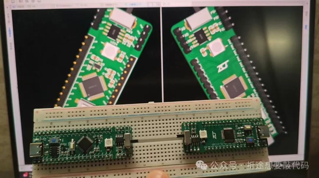
Then, just yesterday, the new board arrived, and after soldering and testing, it worked fine, so today I’m writing this article to open source it.
The engineering files and chip manuals can be downloaded for free by messaging me with the keyword “STC.” I have also open-sourced it on the Lichuang Open Source Square, where you can directly view the engineering files.
https://oshwhub.com/zctnb/works
This board includes STC32G12K128 and STC8G1K08A chips, meaning we can work with two chips at once. I will also release a series of tutorials on STC library functions using this board.
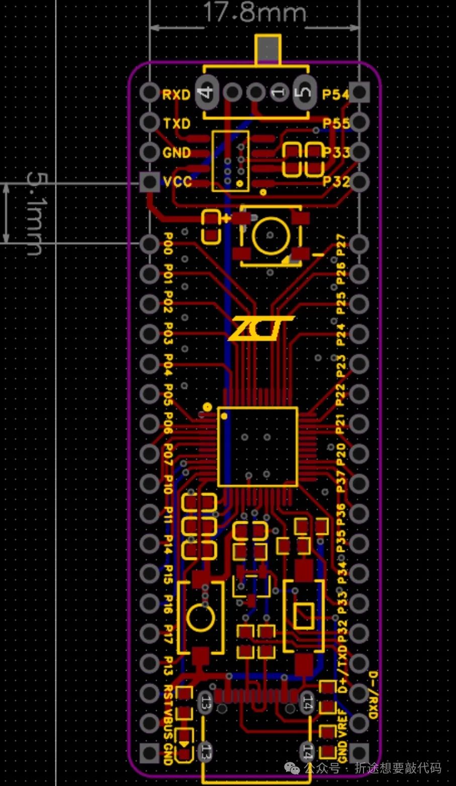
Let’s first take a look at the STC8G1K08A part.
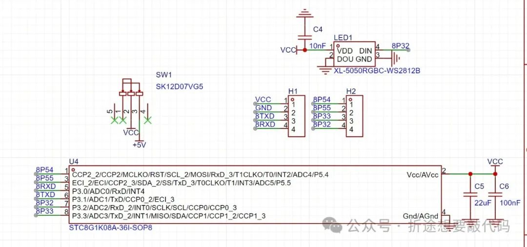
The circuit design is very simple; I used the SOP8 package for the STC8G1K08A, and its peripheral circuit only requires two capacitors.
Additionally, I have routed all eight pins for convenience in programming (requires a USB to serial module), placing RXD, TXD, VCC, and GND on the same row of pins.
I also added a WS2812B, making it less monotonous; the board has a light that allows us to directly check the programming effect, with the data transmission line connected to P32.
For how to light up the WS2812B, you can refer to my previous articles.
Today we will not light the LED; we will light the WS2812B.
Moreover, there is a sliding switch connected to the 5V power supply from USB. When we connect USB and only want to use STC32 without using STC8, we can choose to turn off the power supply to STC8.
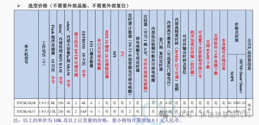
The official suggested retail price for an STC8G1K08A-SOP8 is 0.59 + 0.1, so be cautious of prices when purchasing. I bought it for 0.75, as the price difference was negligible and it was from a store I frequently buy from, so I didn’t mind that small difference. Just make sure not to buy it at an outrageous price.
Also, although it only has eight pins (and two power pins need to be deducted), it still has the necessary resources, so I made a small gadget with it. Once the board arrives and I solder and debug it without issues, I will open source it.
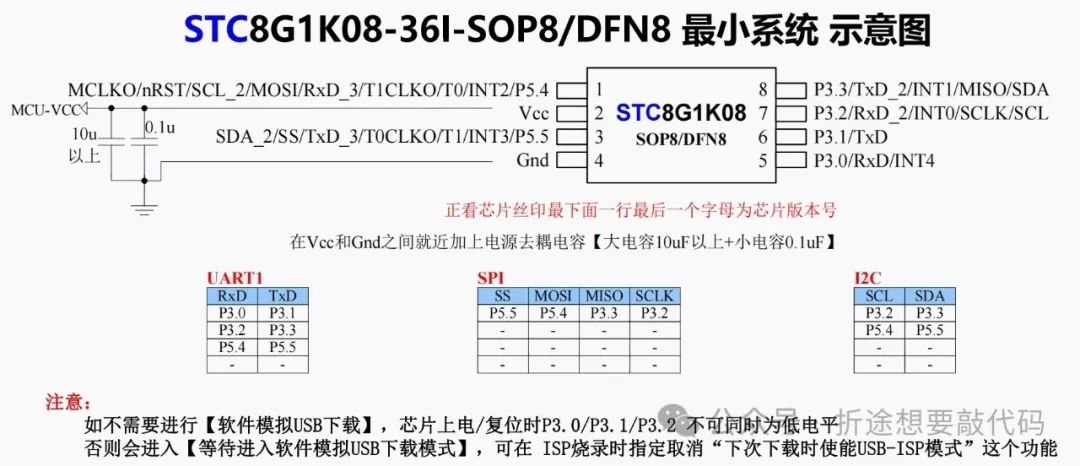
The minimum system diagram provided by the official documentation consists of two capacitors, one above 10μF and one 100nF. While it says above 10μF, 10μF should also be fine. I used 22μF because I had more of those on hand, but you can decide based on your stock; as long as the pad size is the same, you can replace them freely.
Next, we have the STC32G12K128, which has two versions.
The reason is that the first version only supported serial communication, and there was a small issue that prevented programming (details can be found in the previous article linked at the beginning). So, I created a USB version, and later that small issue was resolved, resulting in two versions.
No matter which version, the basic peripheral circuits around the chip remain unchanged. Let’s take a look at these.
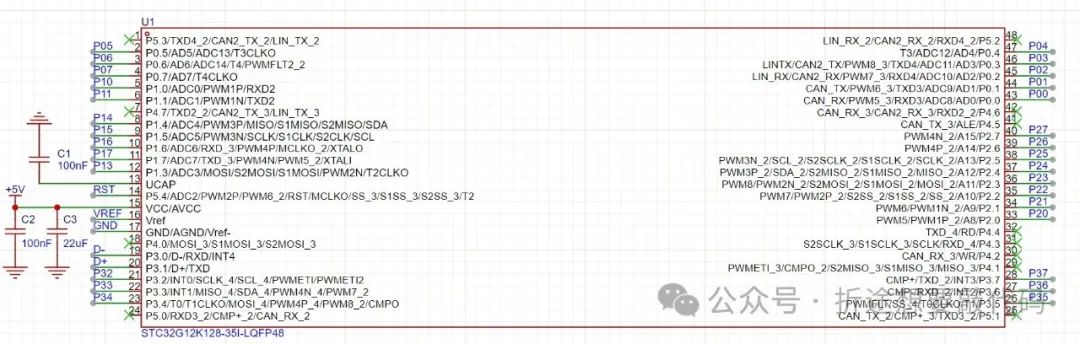
Only three capacitors are needed; yes, just three capacitors, and nothing else including oscillators is required.
The peripheral circuit for STC is that simple; I have fallen in love with it.
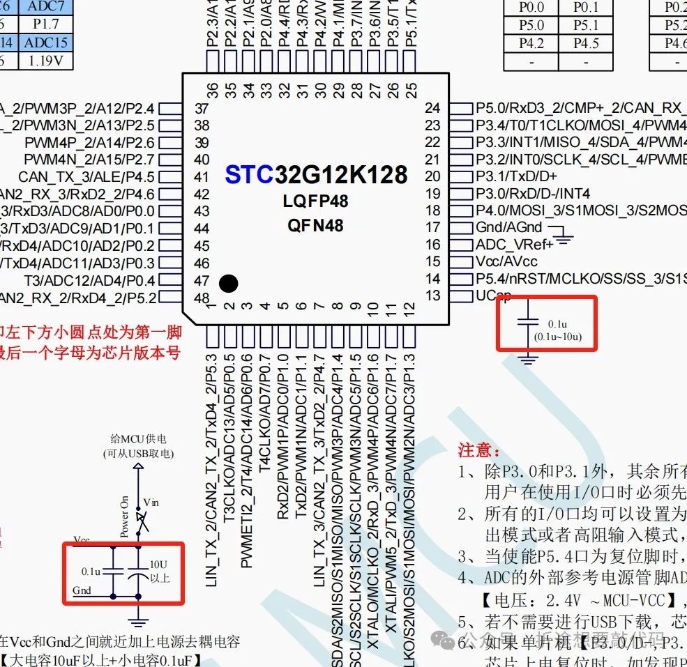
The minimum system diagram in the official documentation looks like this.
Compared to STC8, it adds a 100nF capacitor, with a value that can range from 100nF to 10μF.
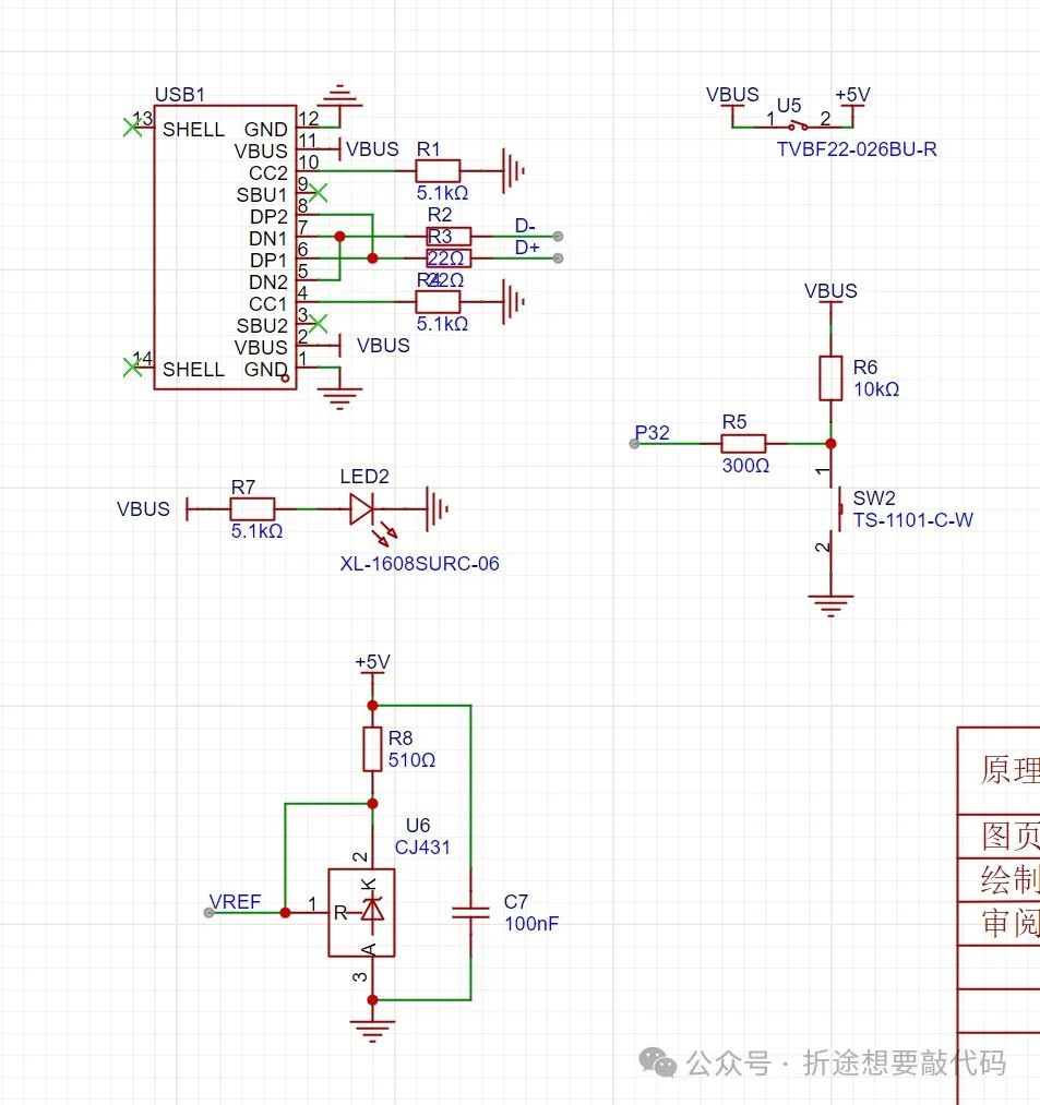
Next, let’s look at the other peripheral circuits for the serial version.
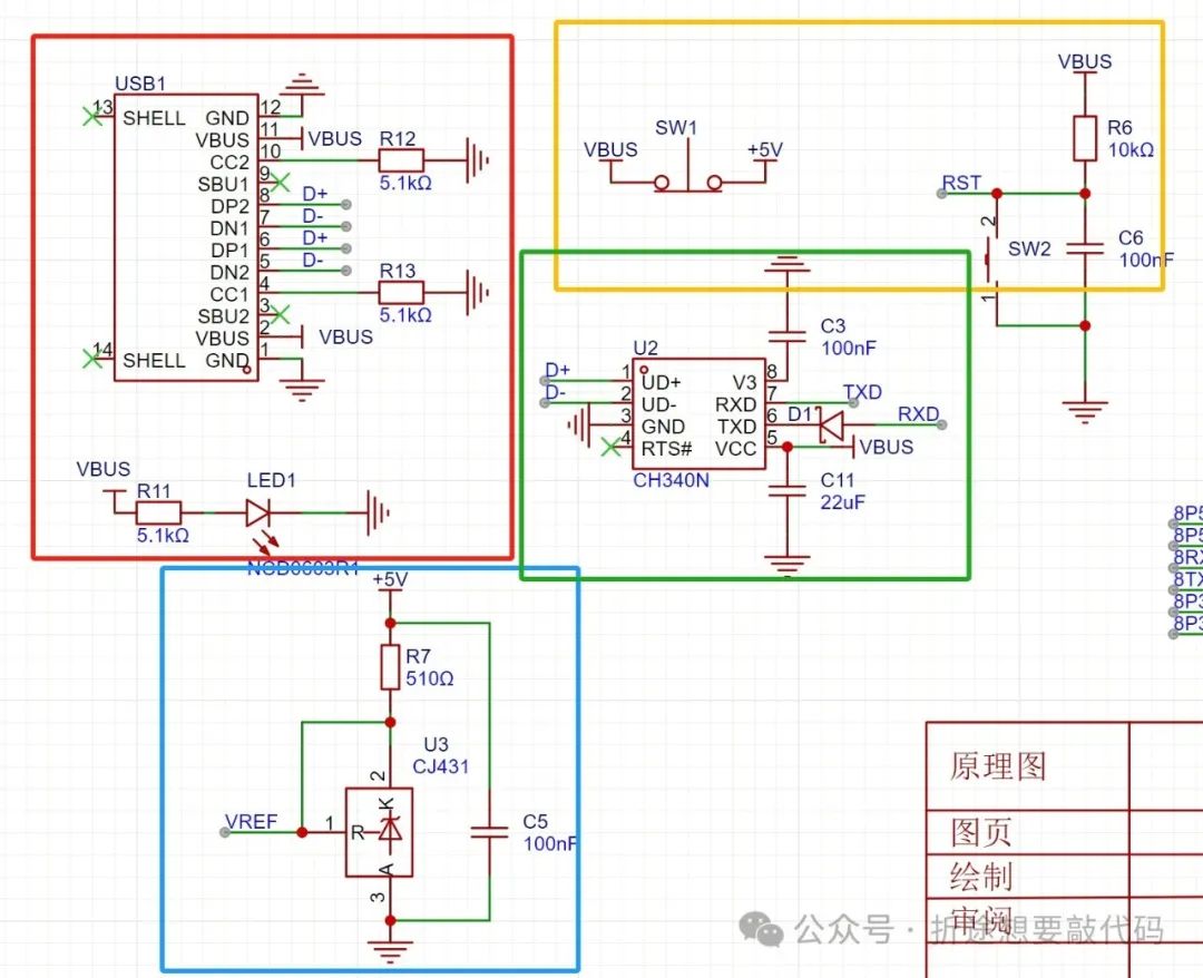
There are a total of four parts.
The red box is the Type-C interface.
The blue box is a reference voltage source borrowed from a project open-sourced by Jialichuang. If you don’t need ADC or if the ADC precision requirement is not high, you can remove this part. My first version was largely copied from this project, and I had some leftover materials, so I kept this part.
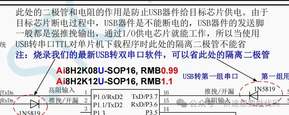
The green box is the USB to serial chip CH340N, and other versions of CH340 are also acceptable. Additionally, the Schottky diode on the TXD of CH340 can be omitted, but I kept it because I had it on hand.
The yellow box contains two buttons; the left one is a normally closed button. Generally, USB directly powers the STC32, and when we press it, the power is cut off, and when we release it, power is restored, allowing the STC32 to cold start, which is necessary for programming.

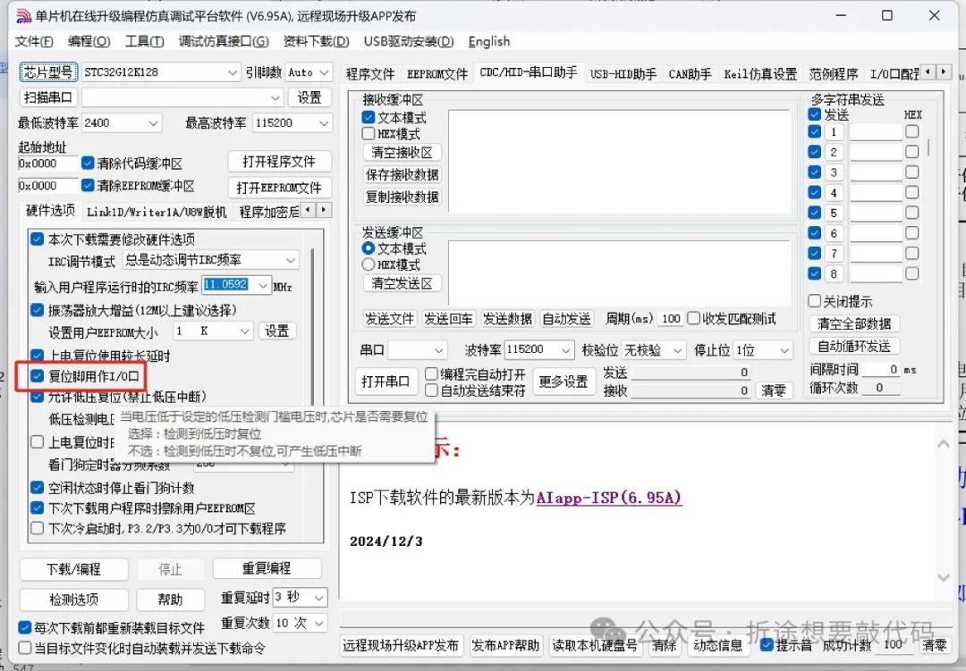
The right button is connected to RST, but by default, it is a regular IO pin. We need to uncheck the box below during programming so that it acts as a reset button.
One thing to note is that in my project files for the serial version, I used a four-layer board, with the inner layers being GND and +5V. Therefore, if you want to make a double-layer board, you need to re-route +5V. I used a four-layer board for convenience; the more layers, the easier the routing.
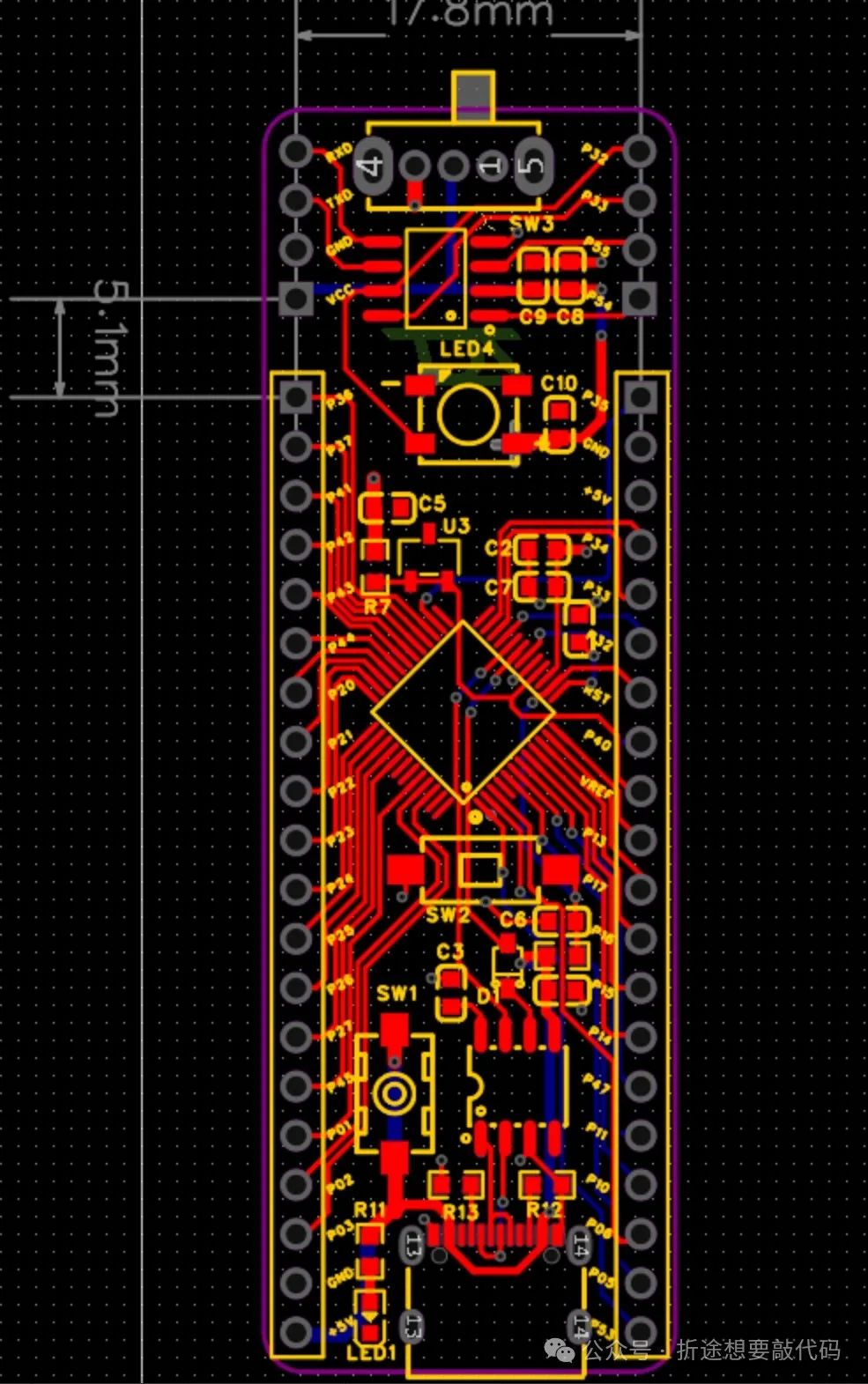
However, the USB version is a double-layer version.
The USB version is simpler; it has no CH340, and I even removed the reset button because I believe there is a reason why they set RST as a regular IO pin. Thus, I removed it. If a reset is needed, simply pressing the normally closed switch can achieve the reset effect.
Additionally, the process for programming differs when using USB compared to serial. We need to ensure P32 is low-level when STC starts, so we need to add a button connected to P32.
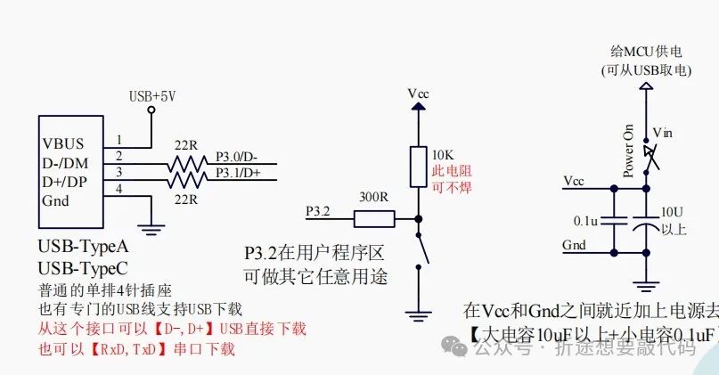
This is reflected in the official manual.
Moreover, we need to place a 22Ω resistor in series on the USB differential signal lines. I forgot to buy it, so I used a 0Ω resistor instead, and it still works fine, so these two resistors can be added or omitted. Adding them will provide better signal transmission stability.
The USB version is shorter than the serial version since it does not include the USB to serial chip.
There is a large empty space between STC32 and STC8, so I added my logo; feel free to replace it.
Also, there are differences in the programming process between the serial and USB versions.
For the serial version, after clicking to program, press the normally closed button to start programming.
For the USB version, you need to hold down the P32 button while pressing the normally closed button. Wait for the programming software to recognize the USB before releasing the P32 button, and then click to program.
With the core board, we can treat it as a packaged function library, moving it wherever needed.
If we need to use this chip for other projects in the future, we can simply copy the schematic of the core board over and re-layout the wiring to use it. Additionally, since most of the chip pins have been routed out, we only need to buy some peripheral modules to learn about the chip.
Thus, the core board is very useful, and I will open-source another one in a few days  .
.

Recently, I’ve been working on my thesis topic, which has been quite stressful. If you have any ideas, please feel free to suggest them (but nothing too difficult; I won’t be able to handle it 

 ; also, nothing too simple; too simple is beneath me, but okay, simple suggestions are also welcome~

 ), if I find your suggestions interesting and feasible, I will try to work on them, and if successful, I will open-source them later.
If I use it as my thesis topic, there will be heavy rewards!