1. Star Topology with Switches
We know that the most basic function and application of a switch is to centrally connect network devices. All network devices (such as servers, workstations, PCs, laptops, routers, firewalls, network printers, etc.) can be directly connected to the switch’s ports as long as the switch’s ports support the corresponding device types, forming a star network. In a star connection, the devices connected to the switch’s ports are equal and can access each other (unless restrictions are applied), rather than assuming, as many newcomers to network management do, that the server connected to the switch is the highest level.
2. Cascading and Stacking Switches
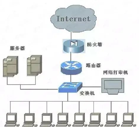
Topology Diagram
The above diagram shows only a basic star Ethernet architecture; actual star enterprise networks can be much more complex. This complexity is not only reflected in how high-end the network devices are and how complex the configurations are, but more importantly, in the complexity of the network switching layers. In enterprise networks, routers and firewalls typically only need to be equipped with one, but switches are usually not just one (except for small networks with around 20 users). If the number of users is larger, such as hundreds or even thousands, cascading or stacking switches is necessary. However, cascading technology and stacking technology differ, and their application ranges are also different.
Cascading switches means connecting switches to each other through switch ports, which solves the problem of insufficient ports on a single switch and also connects clients and network devices that are far from the server room. Since a single segment of twisted pair Ethernet cable can reach 100 meters, each time a switch is cascaded, the distance can be extended by 100 meters. However, this does not mean that cascading can be done arbitrarily; because if the lines are too long, on one hand, the signal will attenuate more along the line, and on the other hand, the lower-level switch still shares the available bandwidth of the upper-level switch’s port. The more layers there are, the lower the available bandwidth for the final client (even if you might be using a hundred-megabit switch), which greatly impacts the network’s connection performance. Therefore, from a practical perspective, it is recommended to deploy a maximum of three levels of switches: core switch – secondary switch – tertiary switch.
The term “three levels” does not mean that only three switches are allowed, but rather that there can only be three levels in terms of hierarchy. Switches connected to different ports on the same switch belong to the same level, so each level can allow several, even dozens of switches to be cascaded. The ports used for cascading can be dedicated UpLink ports or regular switch ports. Some switches come with dedicated cascading (UpLink) ports, while others do not. If there are dedicated cascading ports, it is best to utilize them, as their bandwidth is usually wider than that of regular switch ports, further ensuring the bandwidth of the lower-level switches. If not, cascading can only be done through regular switch ports.
The method of cascading through UpLink ports is shown in the diagram below:
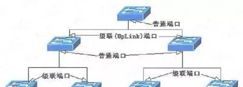
Cascading through UpLink ports
The method of cascading through regular ports is shown in the diagram below:
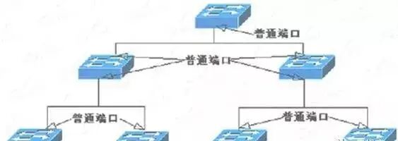
Cascading through regular ports
Note that not only are the ports used different, but the cables used are also different: cascading through UpLink ports requires using regular straight-through cables; while cascading through regular ports requires crossover cables, just like connecting two hosts directly.
As for switch stacking, not all switches can do this; they must have stacking modules. Switch stacking is not done through switch ports but through dedicated backplane stacking modules, using specialized stacking cables for connection. It is important to note that because switch stacks are usually placed in the same location and the connecting cables are shorter, the main purpose of switch stacking is to expand the number of switch ports, not to extend the distance.
At the same time, switch stacking can also increase the available bandwidth of the actual switch ports, as it aggregates the backplane bandwidth of the stacked switches. Thus, the total backplane bandwidth of the switch stack is the sum of the backplane bandwidths of the stacked switches. After the backplane bandwidth is increased, if every port of the switch is utilized, this advantage may not be very obvious (it is still effective, as it is impossible for every port to communicate simultaneously at all times), but if there are free switch ports, the effect will be more pronounced, as it can fully utilize all the bandwidth of the switches.
The stacking connection is shown in the diagram below:
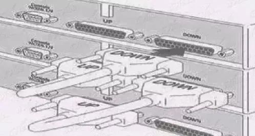
Stacking connection
The stacking connection ports of switches are usually D-shaped connectors, with each switch having two such ports, labeled “UP” and “DOWN” (as shown in the above diagram), indicating the connections for upward and downward stacking, which must not be confused.
3. Routing Connections of Layer 3 Switches
As mentioned earlier, Layer 3 switches also have certain “routing” capabilities, allowing connections between different subnets. However, it should be noted that their routing capabilities are still much weaker than those of routers. The routing function of Layer 3 switches can only be used for interconnection between the same type of networks, and usually only for interconnection between local area network subnets, and cannot connect local area networks to wide area networks or the Internet, as the routing protocols supported by Layer 3 switches are very limited; after all, this is not their primary function.
We know that in a local area network, Layer 2 switches identify the sender of data packets by source MAC addresses and forward data packets based on destination MAC addresses. For a data packet whose destination address is not in the local area network, a Layer 2 switch cannot directly send it to the destination and needs to forward it through a routing device (such as a traditional router). At this point, the switch must be connected to the routing device. If the switch’s default gateway is set to the IP address of the routing device, the switch will send packets that need to be routed to the routing device.
The routing device checks the destination address of the data packet against its routing table. If it finds a forwarding path in the routing table, the routing device forwards the data packet to another network segment; otherwise, it discards the data packet. Dedicated routers are expensive, complex, slow, and can become bottlenecks in the network because they must analyze all broadcast packets and forward some of them, as well as exchange routing information with other routers, and all these processing tasks are handled by the CPU (not dedicated ASICs).
Layer 3 switches can identify and forward data packets using MAC addresses like Layer 2 switches, and can also perform routing between two network segments like traditional routers. Traditional routers use software to maintain routing tables, while Layer 3 switches use dedicated ASIC chips to handle routing and forwarding. Compared to traditional routers, the routing speed of Layer 3 switches is generally ten to several dozen times faster.
The routing connection of Layer 3 switches is shown in the diagram below:
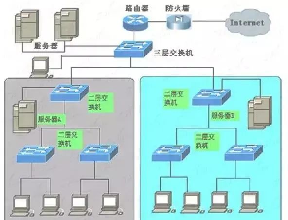
Routing connection of Layer 3 switches
Router’s Local Area Network Connection
Everyone knows that routers can connect enterprise local area networks and wide area networks (such as the Internet), but often overlook another application of routers, which is their local area network connection function. The wide area network connection of routers can refer to the topology diagram and the routing connection diagram of Layer 3 switches.
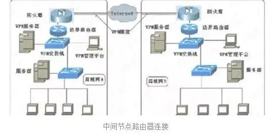
The function of a router depends on the type of router. The routers we commonly refer to are usually boundary routers, which are located at the boundary of different types of networks, as shown in the topology diagram and the routing connection diagram of Layer 3 switches. There is also a type of router designed not for connecting different types of networks, but for connecting different local area networks or different subnets within the same local area network, which is called an “intermediate node router.” Its network structure is shown in the diagram below. It replaces the original Layer 3 switch in the routing connection diagram of Layer 3 switches.
The “boundary router” is located at the edge or end of the network boundary, used for connecting different network routers, which is also the type of most routers currently. As previously mentioned, Internet access routers and the VPN routers to be introduced later are both boundary routers. These routers support a wide range of network protocols and routing protocols, have very high backplane bandwidth, and possess high throughput capabilities to meet the interconnection of various types of networks (including local area networks and wide area networks).
On the other hand, the “intermediate node router” is located within the local area network, usually used to connect different local area networks, serving as a bridge for data forwarding. Intermediate node routers focus more on MAC address memory capabilities and require larger caches. Since the connected networks are primarily local area networks, the supported network protocols are relatively simple, and the backplane bandwidth is also smaller, all of which are aimed at achieving the highest cost-performance ratio to meet the general capabilities of enterprises.
Compared to the routing functions of Layer 3 switches, the routing capabilities of intermediate node routers are certainly stronger, but in a local area network where data exchange is frequent, using intermediate node routers for local area network connections may affect network performance. Overall, if there are many connected local area networks or subnets, and inter-network visits are not very frequent, and the routing is complex, it is best to use an intermediate node router connection scheme. However, in environments with few subnet connections and frequent inter-network visits, it is still better to use Layer 3 switches for connection, which can also save equipment investment, as Layer 3 switches not only have routing functions that meet application needs but can also serve as switches to connect many network devices.