01
Overview
1.1 Introduction
In this lesson, we will create a quiz buzzer: two people will start buzzing at the same time, and the LED light of the person who presses the button first will light up.
1.2 Course Objectives
- Knowledge: Understand the working principle of button switches; how to control the lighting and extinguishing of LED lights.
- Programming Knowledge: Understand what reset means; understand what variables are; master the use of variables to control sensors. Understand what increment operations are. Master the use of multi-condition judgment statements.
- Hardware Knowledge: Master the control methods of LED lights, including: lighting and extinguishing. Master the usage of button switches and how to control other devices.
- English Knowledge: reset: reset; red: red; green: green.
02
Item List
|
Small building blocks |
Several |
|
micro:bit main board |
x 1 |
|
micro:bit expansion board |
x 1 |
|
Red button switch |
x 1 |
|
Red LED light |
x 1 |
|
Green button switch |
x 1 |
|
Green LED light |
x 1 |
|
5V power box |
x 1 |
|
Power cable |
x 1 |
|
3P-PH2.0 to Dupont wire |
x 4 |
03
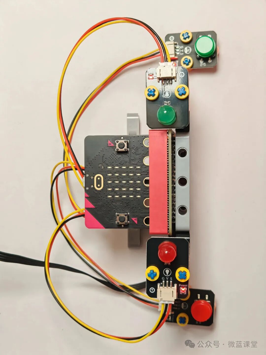
Assembly Process
04
Program Explanation
4.1 Wiring
- LEGO power cable: One end is a LEGO quick connector, connected to the power box; the other end is a DC head, plugged into the DC port of the expansion board.
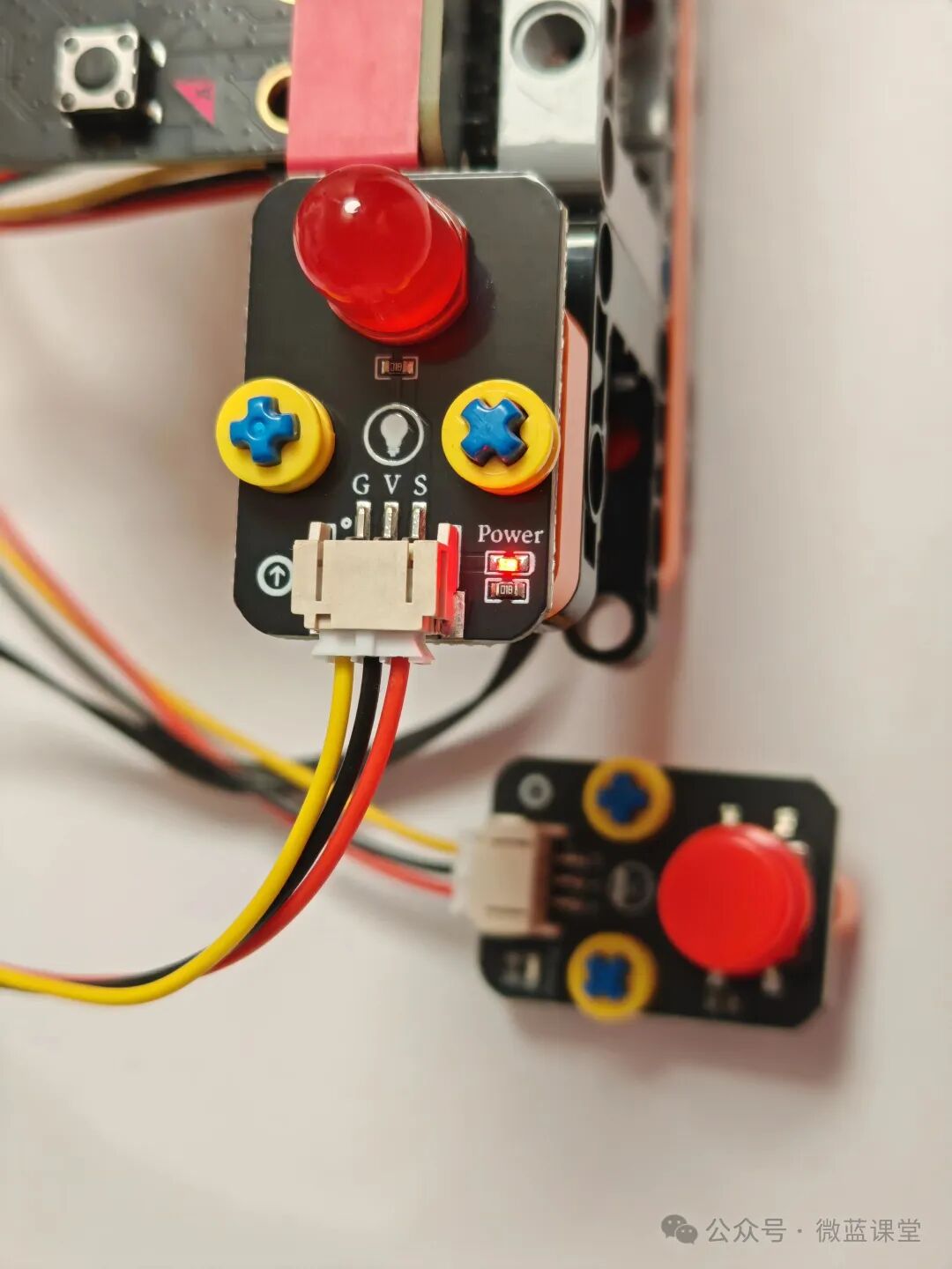
- Red LED light module: PH2.0 end connected to the LED light module, Dupont end connected to the expansion boardP2 row pin, note that the S signal line should be inserted into the S pin of row P2.
- Red button switch module: PH2.0 end connected to the button switch module, Dupont end connected to the expansion boardP9 row pin, note that the S signal line should be inserted into the S pin of row P9.
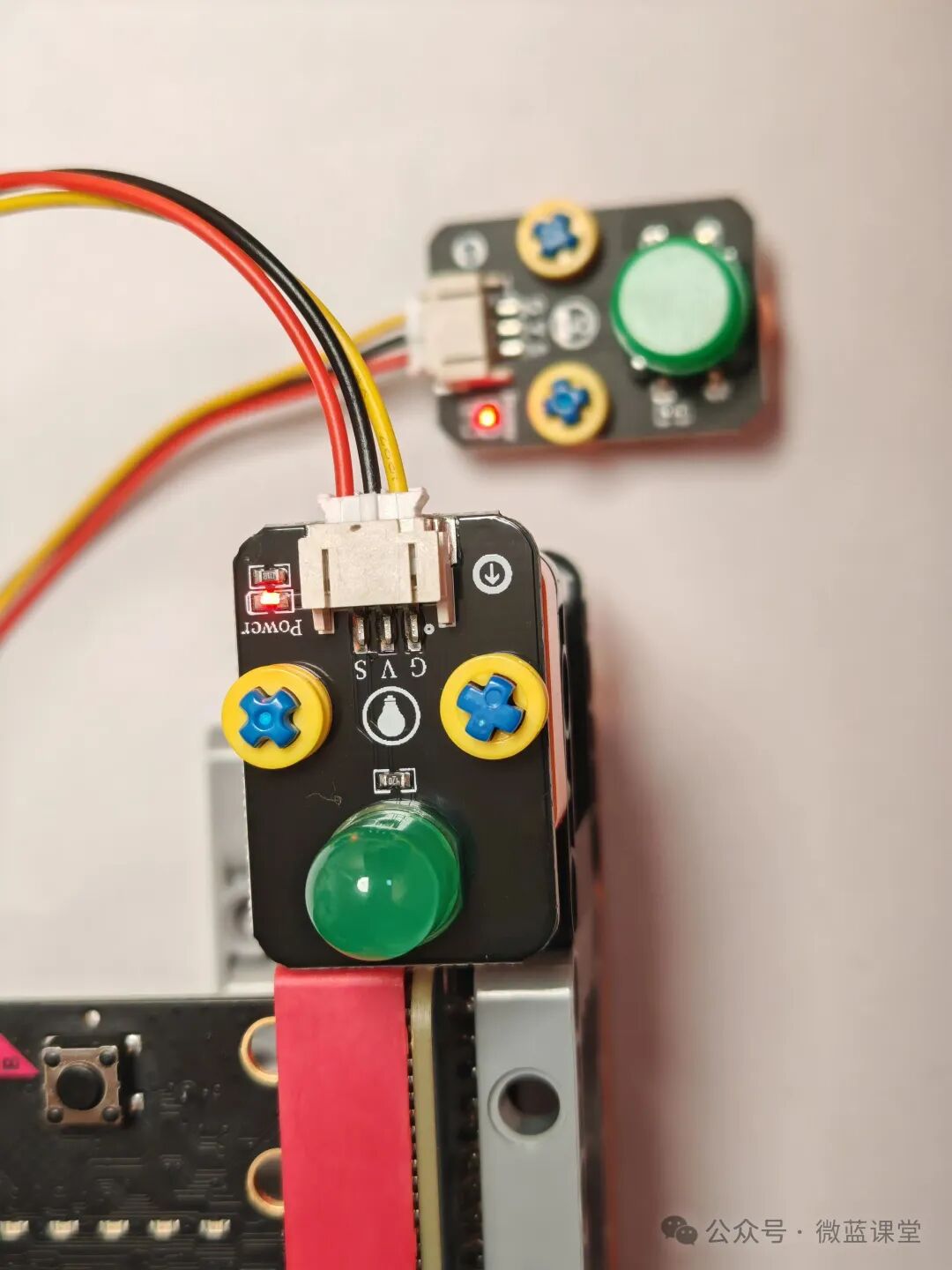
- Green LED light module: PH2.0 end connected to the LED light module, Dupont end connected to the expansion boardP0 row pin, note that the S signal line should be inserted into the S pin of row P0.
- Green button switch module: PH2.0 end connected to the button switch module, Dupont end connected to the expansion boardP1 row pin, note that the S signal line should be inserted into the S pin of row P1.
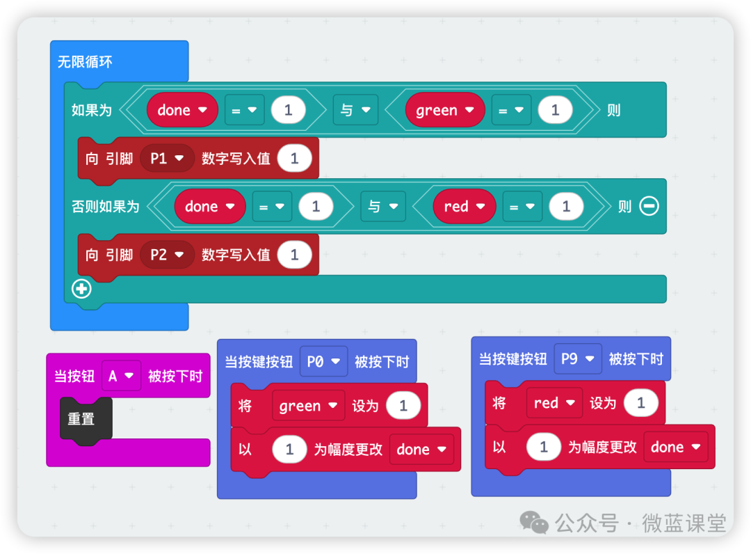
4.2 Program
Program Explanation:
Create a variable called done to count the number of times the button is pressed.
Create a variable called green to control the lighting of the green LED: 1 means it is on.
Create a variable called red to control the lighting of the red LED: 1 means it is on.
When the green button is pressed, which means the P0 pin is pressed, set the green variable to 1 and increment the done variable by 1.
When the red button is pressed, which means the P9 pin is pressed, set the red variable to 1 and increment the done variable by 1.
We then use an infinite loop to check the values of the three variables. When the button is pressed for the first time, which means the done variable equals 1, we check which button was pressed: if green equals 1, the green button was pressed; if red equals 1, the red button was pressed.
Finally, we add a reset code block. Press button A on the micro:bit to start a new round of buzzing.
If both sides press at the same time, neither LED light will light up. Just press button A to start a new round of buzzing.
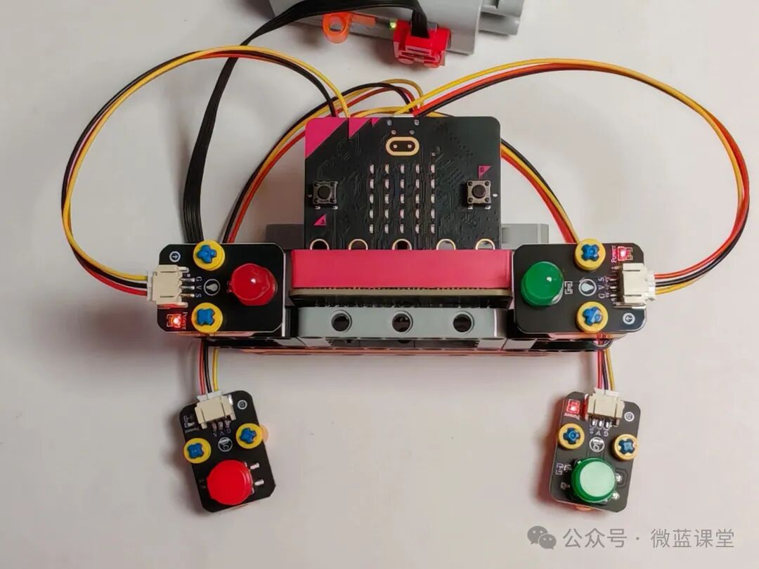
05 – Finished Product Display