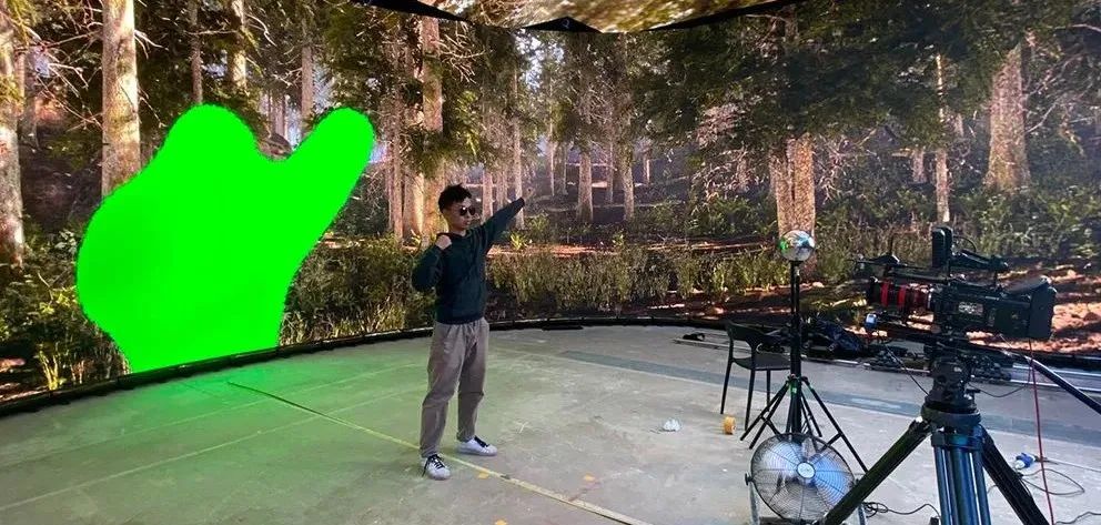
This article was published in Modern Film Technology, 2022, Issue 5
Expert Review
LED virtualization production has become a hot topic in film production in recent years, with its utilization rapidly spreading. Many films both domestically and internationally have adopted LED screens for virtual production. In North America, there are over a hundred LED virtual studios. Although there are still few mature LED virtual studios in China, there are many experimental studios, and numerous experimental reports have been published. These reports provide relatively accurate conclusions, ranging from tests comparing different brands of LED screens to technical requirements for filming. The core purpose of virtual shooting is to achieve “realism” while reducing production costs. The experimental results presented in this paper are an in-depth study of this objective. The results contribute to further research on LED virtualization production and have significant practical implications. The core problem addressed is how to reduce highlight reflection and color spill issues when using LED screens as green screens. The paper creatively introduces the “virtual green screen deformation method based on depth image processing,” combining the green screen compositing method of the “in-camera VFX” with motion capture principles, thus advancing the solution to the problem of integrating real light effects with post-production CG compositing. The author team has obtained several national patents in recent years for their research achievements in virtual shooting, solving multiple key issues in LED background virtualization production. I highly recommend the paper “LED Virtual Real-Time Green Screen Deformation Method Based on Depth Images” to readers and hope they pay attention to other related papers published by the team in Modern Film Technology.
—— Mu Deyuan
Professor and Doctoral Supervisor, Beijing Film Academy
President of the Chinese Society of Cinematographers
Abstract
Film virtualization production based on LED backgrounds is a research hotspot in the film and television production field. This technical solution can display a pure green background on LED screens, compatible with traditional special effects production processes. Addressing the color spill and other issues present when using green screens in LED virtualization production, this paper first conducts comparative experiments to conclude that the size of the virtual green screen is the main factor affecting the shooting effect. It then proposes a real-time deformation method for LED virtual green screens based on depth images, which minimizes the area of the green screen background around the subject, achieving better shooting results. The method is divided into three steps: obtaining and processing depth images, interaction between depth images and game engines, and real-time deformation of the virtual green screen within the view cone. Finally, the paper designs comparative experiments for verification. The experimental results indicate that the proposed real-time deformation method for virtual green screens can significantly reduce the negative impacts of color spill and highlight reflection on the performing subject.
Keywords
Film Virtualization Production Green Screen Keying LED Background Depth Camera
1 Introduction
In 1898, special effects filmmaker Georges Méliès used a black-painted glass plate as a mask to block part of the camera lens, preventing that portion of the film from being exposed. After completing the shooting, he would mask another part of the lens and continue shooting. Through multiple exposures, different scenes would be captured on the same film. This technique is considered the primitive form of green screen compositing technology.
In the following decades, compositing technology entered a rapid development phase, during which techniques such as “black screen technology,” “Dunning blue screen technology,” and “yellow screen technology” emerged based on traditional film production processes[1] . Starting in the 1990s, digital technology rapidly rose, with digital movie cameras gradually replacing film cameras as the mainstream equipment for filmmaking. At the same time, computer-generated imagery became increasingly widely used in film content creation. The filters on digital movie camera sensors are typically arranged in a “Bayer pattern,” which means that the green light-sensitive area is twice as large as that for blue or red light. This arrangement has made green screen keying technology the general solution for color keying techniques today.
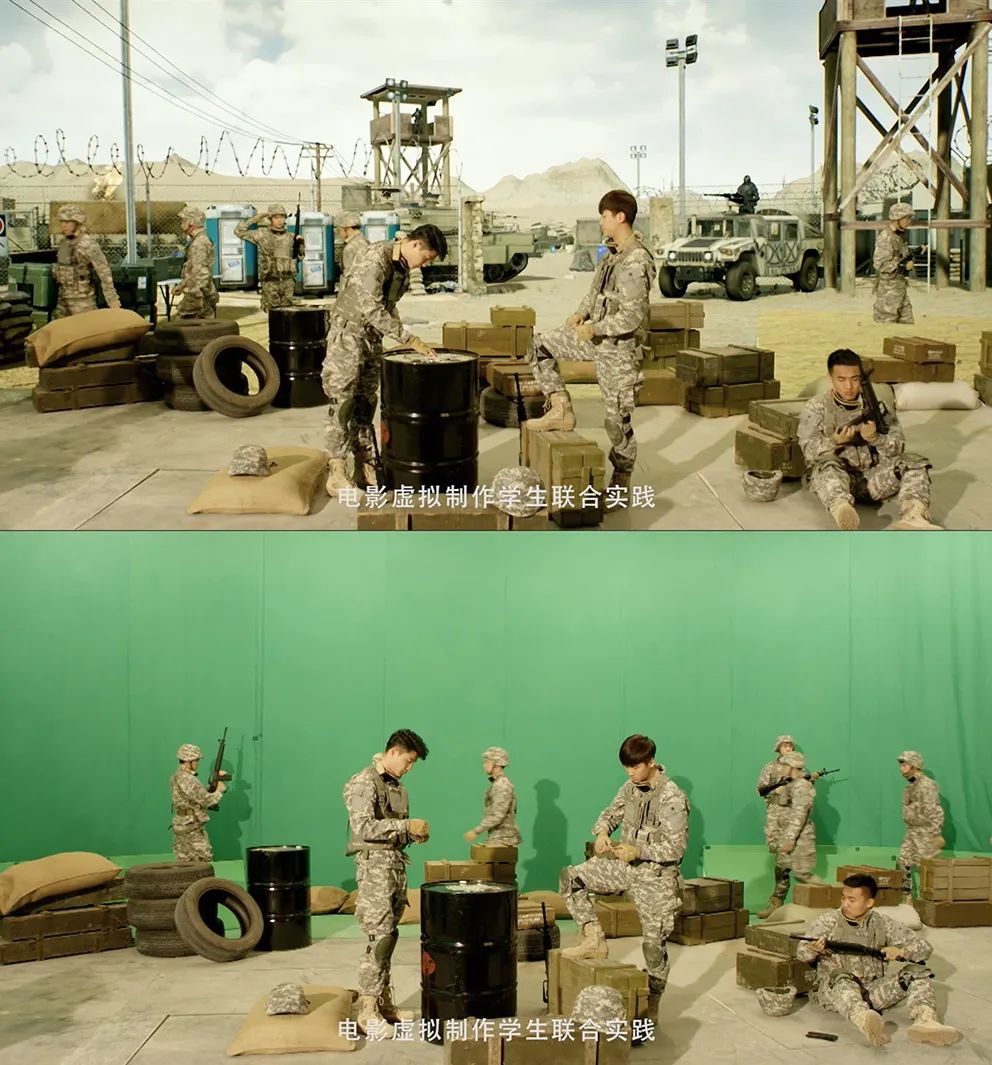
Figure 1 Green Screen Compositing Technology
As shown in Figure 1, placing the shooting foreground against a blue/green screen background, the blue-green background is removed through color keying, resulting in the foreground image. By deploying tracking points on the blue/green screen background, the camera’s motion trajectory can be reconstructed in post-production, achieving a consistent perspective relationship between virtual assets and live-action footage. This technology greatly enhances the creative freedom of shot content, opening up a new realm for film art creation.[2]
2 Disadvantages of Green Screen Compositing Technology and Solutions
In a typical real-time interactive rehearsal process, a large green screen is often set up as the background for color keying, which inevitably leads to some issues[3]: First, there is the problem of dynamic light effect coordination between the real and virtual scenes. The creative team needs to design the dynamic light effects for the final shot before shooting, and based on that, perform dynamic lighting on the actors on-site. Furthermore, to match the on-site lighting information with the lighting information in the post-production 3D scene, a reflective chrome ball needs to be placed in the scene during the shooting of special effect shots to record the on-site lighting information. Secondly, when lighting under a large blue/green screen background, it is easy to produce color spill around the edges of the subject or to reflect the blue/green screen color onto the highlights of the actors or foreground objects, which creates significant challenges for post-production keying. The general solution is to evenly illuminate the green background; otherwise, shadow areas will be difficult to key out, especially behind fine hair or transparent items. The subject needs to be distanced from the green screen to avoid reflective light spilling onto them. Additionally, the foreground subject must be lit with separate light sources to control the exposure and direction of the required lighting in the scene[1]. Lastly, common green screens are often made of a cotton-polyester blended fabric; due to their relatively soft texture, the surface is prone to wrinkles or ripples. Although some special keying sprays can serve as alternatives to green screens, their actual performance is often unsatisfactory.
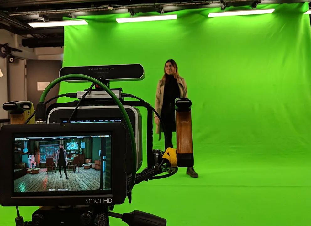
Figure 2 Green Screen in Real-Time Interactive Rehearsal
Overall, these drawbacks are systematic issues inherent to green screen compositing technology, and the solutions summarized by practitioners are merely a reluctant compromise. A fundamental way to avoid these problems is the LED background film virtualization production technology.
The LED background film virtualization production technology (hereinafter referred to as LED virtualization production) captures content that directly integrates visual effects with real scenes, achieving the so-called in-camera VFX shooting effect[4]. This technology greatly improves the shortcomings of real-time interactive rehearsals by using LED background walls to replace blue/green screens with real-time rendered 3D scenes. The light emitted by LED modules of the same model should theoretically be completely uniform, which mitigates the issues of uneven reflection or wrinkles often found in traditional blue/green screens. Additionally, by removing the large green screen, it completely resolves the issues of color spill and reflection from blue/green screens. Finally, the LED background wall provides high-fidelity real environmental lighting without the need for post-production light matching, significantly enhancing the realism of the lighting effects within the shot.
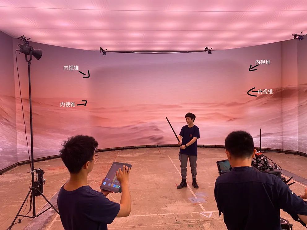
Figure 3 Inner and Outer View Cones
In a typical LED background film virtualization production process, the rendered images displayed on the LED background wall are divided into two parts, referred to as the inner view cone and outer view cone[5] (Figure 3). The outer view cone does not require rendering high-precision images but instead transforms the LED panel into a dynamic light source to replicate the effect of light hitting real-world locations. When the camera moves, the outer view cone image remains static, mimicking the principle that lighting and reflections in the real world do not move with the camera, thus providing actors and foreground objects with authentic dynamic environmental lighting. The high-quality real-time rendered image within the camera’s field of view (FOV) is called the inner view cone, and its perspective relationship changes with the camera’s position to achieve in-camera VFX shooting.
However, this solution still has some issues. Firstly, the dense and orderly arrangement of the LED panel’s light beads can produce moiré patterns when the camera focuses on the LED panel, affecting the final image quality. Secondly, due to the limited rendering capabilities of current 3D real-time engines, the rendering quality for some very complex effects is unsatisfactory and cannot meet the requirements for final shots captured directly after filming. Therefore, in such cases, a pure green background can be displayed on the LED screen to maintain compatibility with traditional special effects production processes.
Thus, for certain shots in LED virtualization production, the inner view cone can be replaced with a pure green image with tracking point patterns to provide post-production keying material, while the outer view cone can still offer authentic dynamic environmental lighting. This solution combines the advantages of both processes, providing better convenience and usability (Figure 4). By replacing the inner view cone entirely with a solid color, the image captured within the camera’s field of view will be a solid color except for the actors and foreground objects. LED screens are self-emitting lights, offering higher brightness and saturation compared to traditional blue/green screens, which are diffuse reflectors. Therefore, in the LED background virtualization production process, common techniques used in traditional green screen compositing cannot be applied. This paper analyzes the controllable factors that have the greatest impact on the existing process and studies and realizes a novel solution.
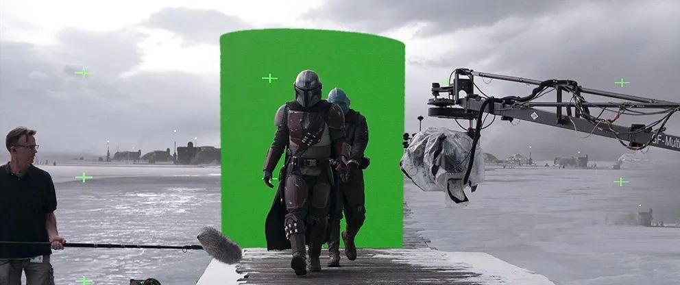
Figure 4 Behind-the-Scenes Production of The Mandalorian
3 Analysis Experiment on the Impact of Virtual Green Screens on Foreground
To analyze the extent of the impact of virtual green screens in LED virtualization production on shooting effects, this paper conducts relevant test experiments on different influencing factors.
3.1 Impact of Inner View Cone Green Screen Size on Shooting
In LED virtualization production, using the inner view cone as a green screen while the outer view cone continues to display the virtual 3D scene is one of the commonly used shooting methods, aimed at restoring the reflections on the subject (as seen in The Mandalorian)[6]. The size of the inner view cone directly affects the shooting effect of the foreground object. Therefore, the research team first designed comparative experiments to analyze the color spill and reflection situations caused by different sizes of the inner view cone green screen in current LED virtualization production. The experimental site is shown in Figure 5.
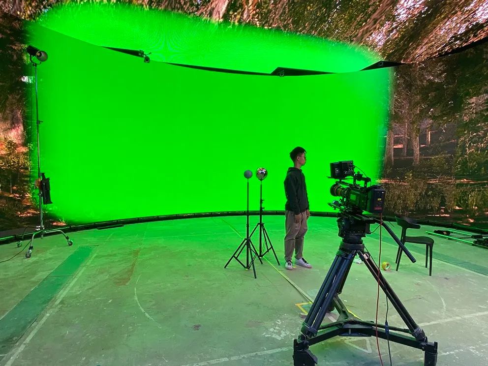
Figure 5 Experimental Site
In LED virtualization production, to ensure that the inner view cone image completely covers the camera’s shooting range, the size of the inner view cone changes with the focal length of the lens. The shorter the focal length, the larger the field of view, and thus the larger the inner view cone.
This experiment varied the size of the inner view cone, observing the performance of color spill and reflection under different conditions. To facilitate observation and comparison, the actual focal length of the camera was kept constant, and the results are shown in Figure 6. The larger the inner view cone, the more severe the color spill on the gray ball and the person’s face, and the larger the area of green reflection on the chrome ball and sunglasses.
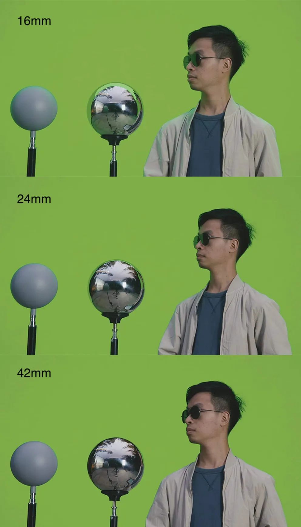
Figure 6 Comparison of the Impact of Inner View Cone Size on the Image
When shooting with a long focal length and a smaller inner view cone, it is basically impossible to observe significant color spill, and there is almost no green on the reflective objects. However, the green reflected in the sunglasses may vary depending on the actor’s head orientation; when the actor’s head turns to a certain angle, the sunglasses may reflect the green LED background into the lens. But the smaller the inner view cone, the lower the probability of this happening.
Therefore, a preliminary conclusion can be drawn: the size of the inner view cone greatly impacts color spill and highlight reflection on the foreground and should be minimized as much as possible.
3.2 Impact of Inner View Cone Green Screen Brightness on Shooting
The green screen displayed on the LED background wall is not only uniformly flat but also has adjustable brightness. Appropriate green screen brightness helps improve keying processing and also affects the color spill and highlight reflection of the subject.
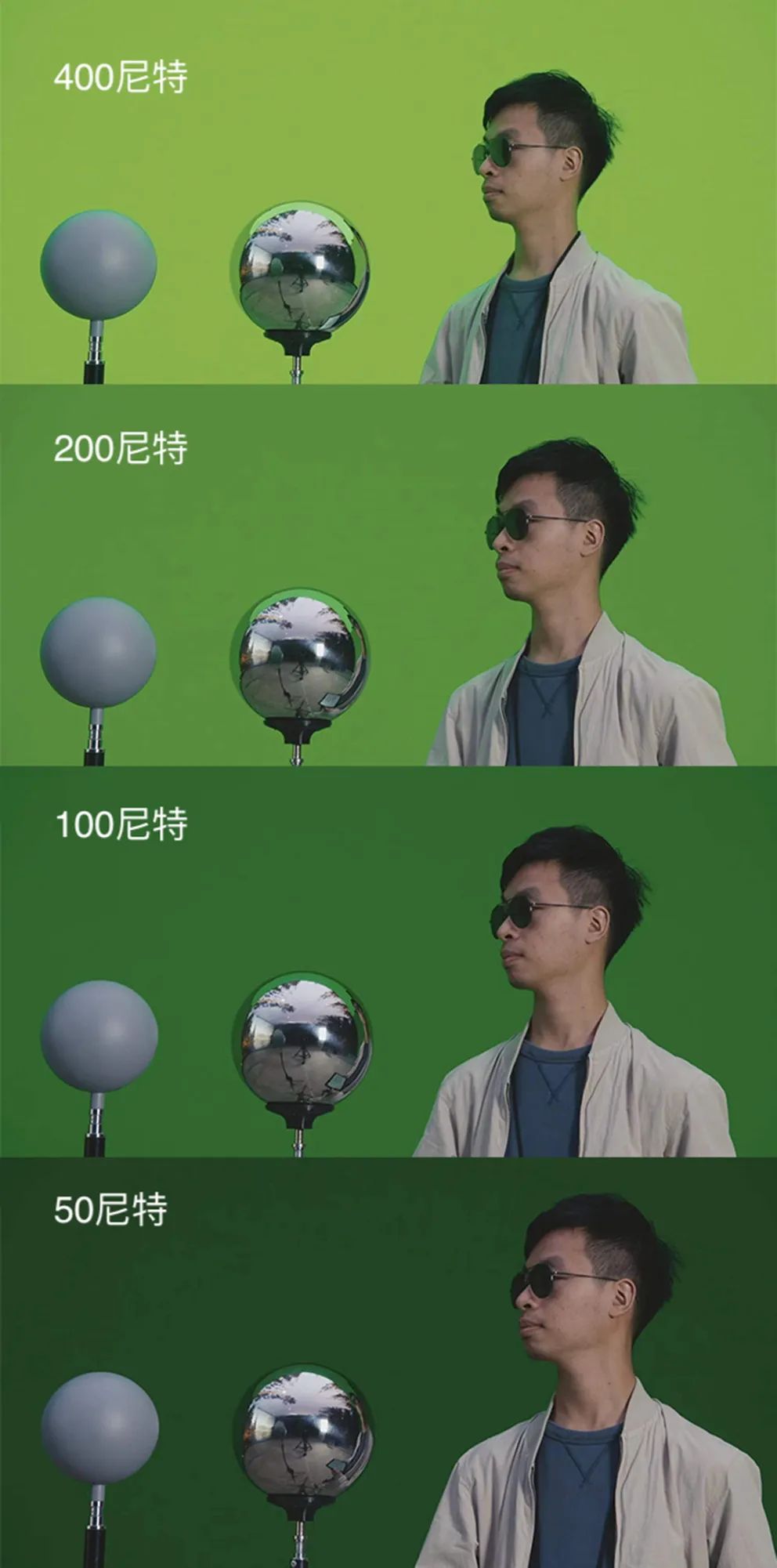
Figure 7 Comparison of the Impact of Inner View Cone Brightness on the Image
In the comparative experiment on inner view cone brightness, the person was positioned 4 meters from the screen, with an illuminance of about 200 lux at the position when the inner view cone green screen was off, and the inner view cone size was set to a 16mm focal length field of view. As shown in Figure 7, when the inner view cone green screen brightness was 400 nits, significant color spill appeared on the person and the gray ball’s surface, while at 100 nits, the color spill was generally acceptable.
From the edges of the gray ball and chrome ball, it can be seen that the highlights and color spill decrease as the brightness of the LED screen decreases. When the inner view cone brightness is at 50 nits, there is still a visible green edge on the chrome ball’s surface, but further reducing the brightness may hinder post-production keying. In practice, the brightness of the lighting source, the distance between the subject and the green screen, and other factors also affect color spill. Color spill is essentially determined by the ratio of the intensity of the lighting source to the light reflected from the green screen. Therefore, in actual production processes, the appropriate LED background brightness should be selected based on the on-site environment and lighting conditions, and blindly pursuing low brightness is inadvisable.
From the above two sets of experiments, it can be concluded that both the size and brightness of the inner view cone significantly affect the color spill and highlight reflection of foreground objects. Additionally, some other influencing factors, such as the color saturation of the virtual green screen and the brightness of the on-site light sources, were not tested due to conditions. Among these, the size of the inner view cone has a considerable negative impact on the highlight reflection of the foreground, which cannot be completely eliminated by reducing brightness. Therefore, we believe that the size of the inner view cone is a more critical factor. In actual production processes, brightness selection will depend on the lighting conditions and the creative intentions of the creative team. Thus, to reduce the highlight reflection of color spill on foreground objects, the size of the inner view cone should be minimized as much as possible.
4 Principle and Implementation of Virtual Green Screen Real-Time Deformation Scheme
To mitigate the issues caused by displaying pure colors throughout the inner view cone, this paper proposes a virtual green screen real-time deformation method based on depth image processing. This method utilizes the depth image information from the captured footage to separate the actors and other subjects from the LED background wall, and then applies the separated depth information in the form of a mask to the inner view cone, ensuring that the captured subjects are entirely surrounded by the green screen in the camera’s view, thus minimizing the area of blue/green screens while effectively avoiding color spill and green screen issues in film production.
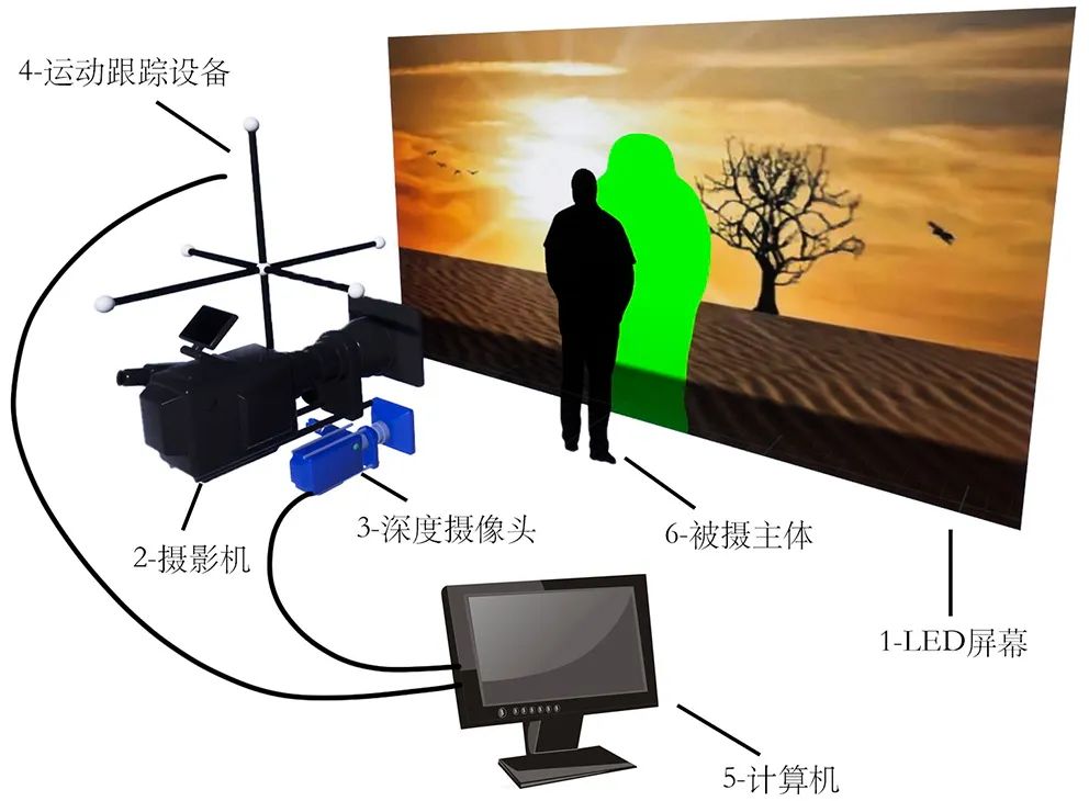
Figure 8 Schematic Diagram of Virtual Green Screen Deformation Principle
As shown in Figure 8, this experimental scheme binds a depth camera with a regular camera to simultaneously capture the subjects. In the footage captured by the camera, the subjects should be surrounded by a green screen slightly larger than their outline, while the remaining part of the LED background wall displays the outer view cone image provided by the 3D real-time engine.
This experiment utilized the RealSense L515 depth camera based on ToF technology to capture depth information. We do not need to identify the precise depth of the subjects; we only need to distinguish the foreground subjects from the LED background wall to obtain the required depth map as a mask.
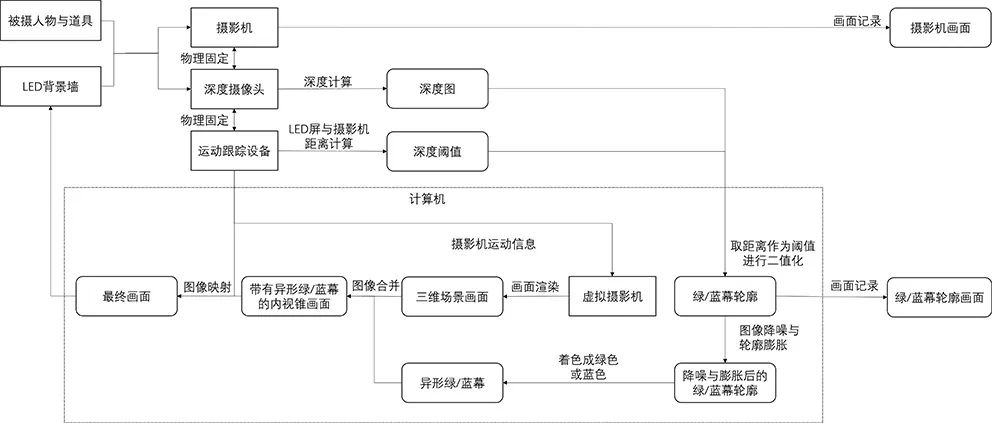
Figure 9 Technical Flowchart of Virtual Green Screen Deformation Method
The specific process is shown in Figure 9. The depth camera captures the depth information of the scene, and the computer processes this depth information, which is then transmitted in real-time to the 3D real-time engine as a depth map. Meanwhile, the camera tracking device measures the distance from the camera to the LED background wall, using this distance as a critical threshold to binarize the depth map, ensuring that the subjects in front of the LED screen are white while the LED screen itself is black. Then, through the interface provided by the depth camera, the binarized blue/green screen outline is sent to the 3D real-time engine.
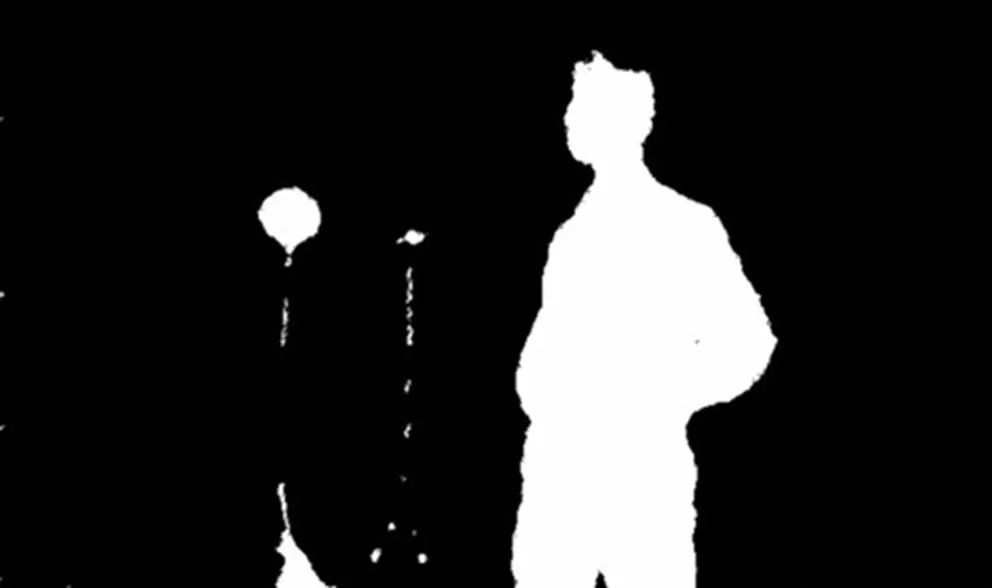
Figure 10 Schematic Diagram of Binarized Depth Map
To capture footage suitable for normal keying, the white area of the green/blue screen outline must completely cover the subjects. Therefore, the green/blue screen outline needs to undergo dilation processing (as shown in Figure 11). The implementation idea is to displace the depth map in multiple directions on the plane and then overlay them, as shown in the blueprint function in Figure 12.
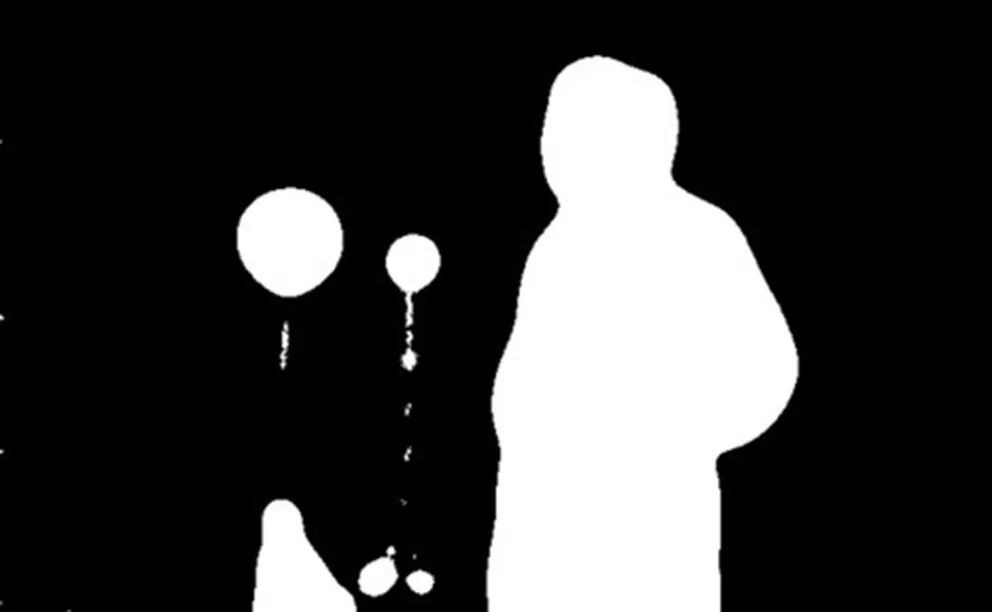
Figure 11 Schematic Diagram of Dilation Processed Depth Map
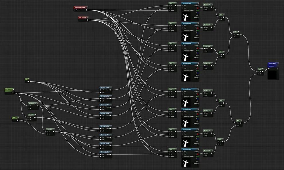
Figure 12 Implementation of Dilation Function in UE4
The size of the dilation of the LED green screen outline can be determined based on specific shooting conditions such as focal length, lens movement speed, etc. To avoid image delay, when shooting fast-moving shots, the dilation value should be appropriately increased.
The dilated LED green screen outline is then colored and mapped to the LED background wall based on the camera’s position tracking information, and finally, the camera records the footage. The achieved effect is shown in Figure 13.
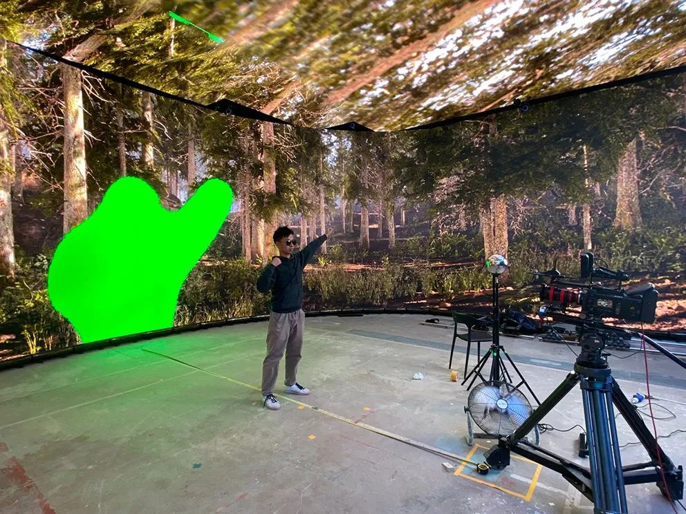
Figure 13 Achieved Effect Diagram
After shooting, post-production keying compositing is required. The footage captured in this production method only has a ring of green screen surrounding the subjects, and keying alone cannot complete the production. Therefore, a corresponding post-production keying compositing method is proposed.
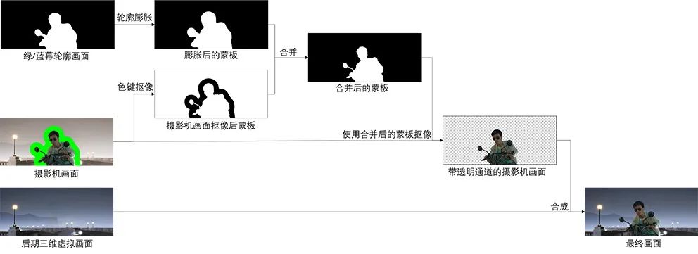
Figure 14 Keying Process Flowchart of Virtual Green Screen Deformation Method
The post-production keying method process is shown in Figure 14. The footage recorded by the camera on-site undergoes color keying to obtain a mask, while the green/blue screen outline recorded on-site is also processed through dilation to obtain another mask. Notably, the dilation value here should be slightly smaller than the dilation value used during on-site shooting. The two masks are then overlaid to obtain a combined mask, which is used for keying the camera footage and compositing with the post-production 3D virtual scene to complete the production.
5 Testing and Discussion of the Application Effects of Virtual Green Screens
To verify the practicality of this method and system, this paper designs comparative experiments among the fully green LED background wall, inner view cone green screen, and virtual green screen to validate their performance in color spill control and mirror reflection issues. In the validation experiment, the camera and lens parameters remain consistent, comparing the performances of the fully green LED background wall, inner view cone green screen, and virtual green screen in capturing gray balls, chrome balls, and character shots. The experimental site is shown in Figure 15.
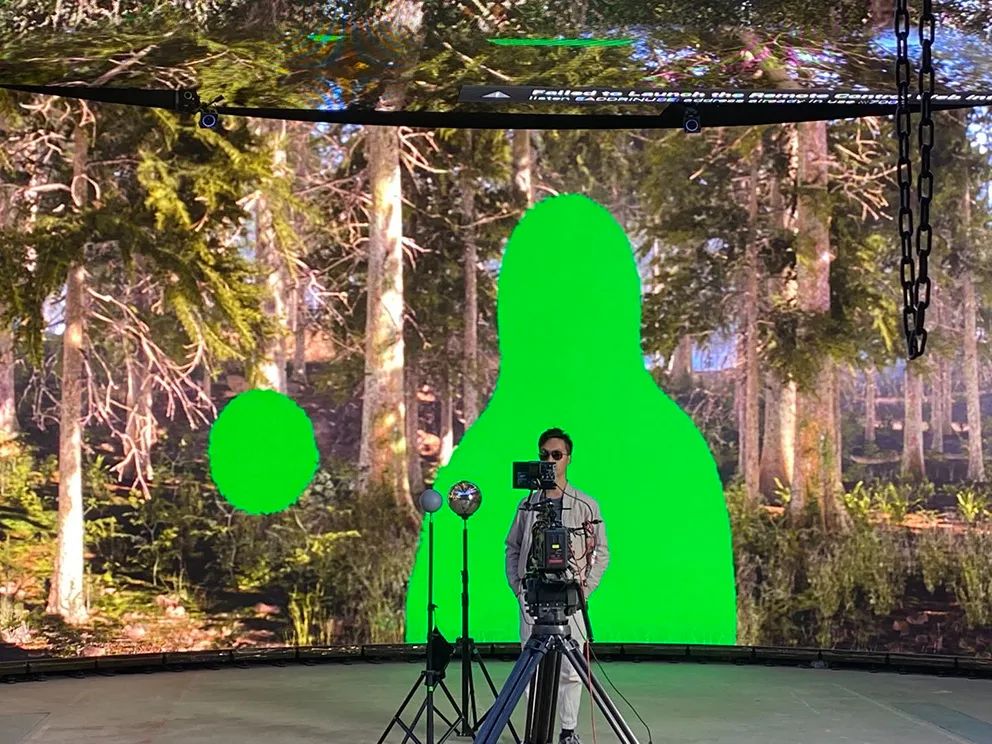
Figure 15 Experimental Site Diagram
(1) Color Spill Test: The gray ball was filmed under the conditions of the fully green LED background wall, inner view cone green screen, and virtual green screen to observe its color spill situation. Under the fully green LED background wall, the color spill almost filled the entire gray ball, making keying extremely problematic. Under the inner view cone green screen, only the edges exhibited color spill. In contrast, under the virtual green screen condition, the gray ball showed almost no color spill, as illustrated in Figure 16.
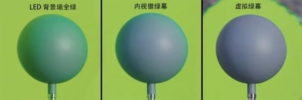
Figure 16 Color Spill Conditions of the Gray Ball Under Different Green Screen Types
(2) Reflection Test: The reflection of the chrome ball was observed under the fully green LED background wall, inner view cone green screen, and virtual green screen conditions. As shown in Figure 17, under the fully green LED background wall, the entire chrome ball exhibited green spill; under the inner view cone green screen, there was some improvement, but significant green screen spill was still present. In the virtual green screen condition, only a small area of green screen spill was observed on one side, while most of the image displayed the virtual scene content, better restoring the reflections of the subject in the scene.
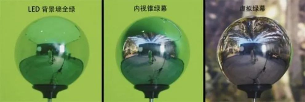
Figure 17 Reflection Images of the Chrome Ball Under Different Green Screen Types
(3) Actor Test: Characters were filmed under the fully green LED background wall, inner view cone green screen, and virtual green screen conditions to observe their effects. As shown in Figure 18, from left to right are the conditions of the fully green LED background wall, inner view cone green screen, and virtual green screen regarding the skin and sunglasses of the characters. The color spill situation improved from left to right, with almost no color spill in the virtual green screen condition. The reflections in the sunglasses indicate that under the fully green LED background wall and only the inner view cone displaying pure green, the surface of the sunglasses reflected green significantly. However, using the virtual green screen, the negative impacts of color spill and reflection were virtually undetectable to the naked eye, and the image reflected in the sunglasses accurately restored the virtual environment of the actor, effectively addressing both green screen keying and mirror reflection issues.
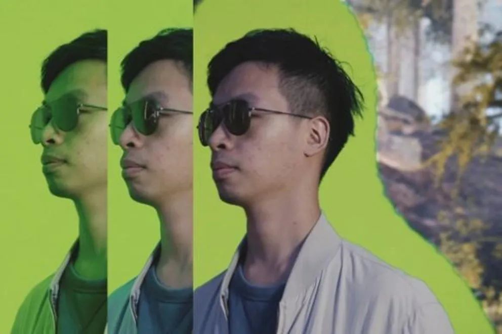
Figure 18 Performance of Character Skin and Sunglasses Under Different Green Screen Types
In summary, the virtual green screen real-time deformation method based on depth information acquisition proposed in this paper can effectively improve the issues of color spill and reflection in LED virtualization production. Compared to manually adding small areas of green screens in the LED background wall, this method can automatically adjust the green screen’s position in real-time according to the camera’s orientation, ensuring that the green screen always surrounds the captured subject without requiring manual adjustments to change the green screen’s display position during camera movement.
Due to experimental conditions, we were unable to set up a traditional green screen environment of the same size for controlled variable experiments. The fully green LED background wall can be somewhat analogous to the traditional green screen situation for reference.
However, this solution also has some issues. Firstly, the LED green screen can only be displayed on the LED background wall. If the background of the subject includes the ground, traditional green screens are still needed, as the floor is often used for arranging foreground interactions with characters.
Secondly, due to the complexity of this system, video signals must pass through depth cameras, game engines, and digital signal distribution systems, which can lead to significant delays. For rapidly moving objects, such as an actor’s arms, the virtual green screen may not respond in time on the LED screen.
Finally, the experiment utilized a laser ToF-based depth camera, which has limited accuracy, low image resolution, and some noise, making it difficult to identify smaller objects. Additionally, the depth recognition of black light-absorbing objects and mirror-reflective objects requires further improvement.
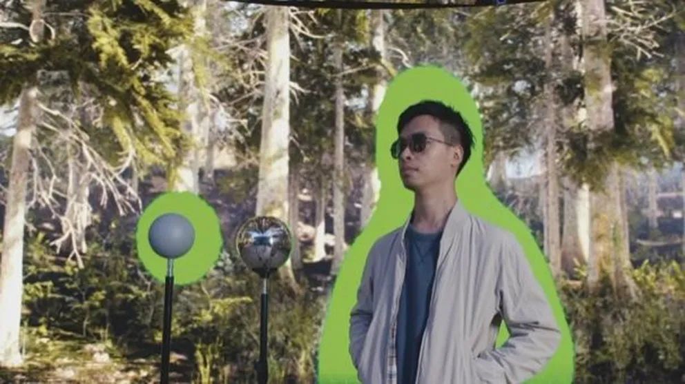
Figure 19 Virtual Green Screen Deformation Method Based on Depth Image Processing
6 Summary and Outlook
LED background film virtualization production is currently one of the most advanced film and television production technologies. Displaying a virtual green screen background on LED walls provides a flat image that can be conveniently adjusted for size and brightness and allows for the addition of markers, making it compatible with traditional green screen shooting for specific shots. This paper studied the factors influencing the effects of LED virtual green screens on shooting outcomes and proposed a virtual green screen real-time deformation method based on depth image processing. By minimizing the size of the LED virtual green screen, the negative impacts of green light emitted from the LED panel on the performing subject’s color spill and highlight reflection were minimized, resolving the inner view cone green screen compositing issues in LED virtualization production.
Due to influences from experimental environment, equipment accuracy, and system complexity, the proposed technology has some limitations and applicable scopes. We will further research these aspects in future work, continuously improving and developing technologies related to LED background film virtualization production to promote the application of new technologies.
Notes and References
(Scroll down to read)
① Image source: https://www.fxguide.com/fxfeatured/vanishing-points-vector-for-virtual-production/.
[1] FOSTER J. The Green Screen Handbook: Real-World Production Techniques [M]. Routledge, 2014.
[2] Chen Jun. “Virtual” Technology, “Real” Means—Discussing the Impact of Film Virtualization Production Technology on Film Creation [J]. Journal of Beijing Film Academy, 2019(01): 119–124.
[3] Wu You. Analysis of the Virtual Production Technology of The Mandalorian and StageCraft [J]. Modern Film Technology, 2020(11): 6–12.
[4] Chen Jun, Zhao Jianjun, Lu Bohong. Research on Key Technologies of Film Virtualization Production Based on LED Background Walls [J]. Modern Film Technology, 2021(08): 17–25.
[5] In-Camera VFX Overview [EB/OL]. [2021-12-27]. https://docs.unrealengine.com/4.27/en-US/WorkingWithMedia/IntegratingMedia/InCameraVFX/InCameraVFXOverview/.
[6] The Mandalorian: This Is the Way—The American Society of Cinematographers [EB/OL]. [2021-12-27]. https://ascmag.com/articles/the-mandalorian.



Supervising Unit: National Film Administration
Organizing Unit: Film Technology Quality Inspection Institute
Publication Number: CN11-5336/TB
International Standard Serial Number: ISSN 1673-3215
Submission Email: [email protected]
Official Website: www.crifst.ac.cn
Advertising Cooperation: 010-63245083
Journal Distribution: 010-63245082