1
Introduction
PLCs have many instructions, but in actual projects, you may only use about 60% of them, or even less. The key to learning PLCs is not just to learn these instructions, but to understand how to use them to design control programs and debug projects. Many beginners learn a lot of instructions when starting with PLCs, but when it comes to completing a device program, they often don’t know where to start. Today, I will share a very simple device control case: “Pneumatic Screen Pressing Device”.
2
Case Description
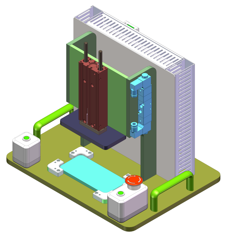
Application scenario description:The pneumatic pressing fixture achieves precise pressing of workpieces or products through the transmission and control of air pressure, widely used in electronic product manufacturing, for pressing shielding covers on circuit boards, and for the assembly of components. Process action description:To prevent accidents, this device requires dual-hand operation to start. The device mainly consists of the processes of the pressing cylinder descending, holding pressure, and the pressing cylinder ascending. Device action description:The pneumatic screen pressing fixture is used for pressing mobile phone screens. Detailed actions: 1) In manual mode, the cylinder can be controlled to move up and down.2) In automatic mode, when a workpiece is detected, both hands must press the start button, and the cylinder descends. It holds the pressure for 5 seconds, then the cylinder ascends. The product is removed, completing the process.3) The device should be designed with an alarm program to troubleshoot issues.
3
Case Program Writing
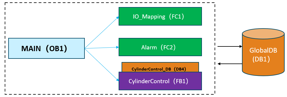
Program structure:According to the control requirements, this case program consists of three parts: IO mapping program, alarm program, and cylinder action control program (including manual and automatic programs).
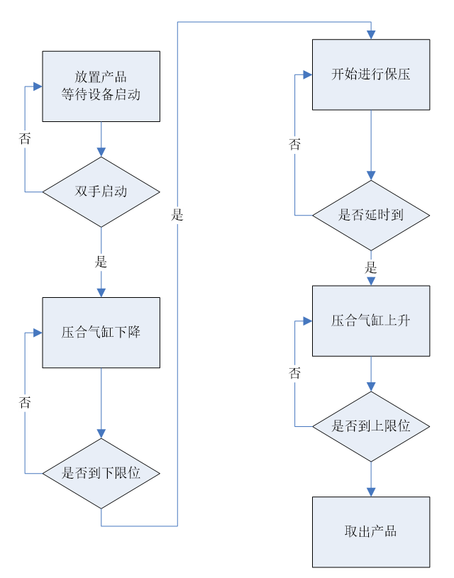
Program action flow:To prevent accidents, this device requires dual-hand operation to start (i.e., both buttons must be pressed simultaneously to start the device). The device mainly consists of the processes of the pressing cylinder descending, holding pressure, and the pressing cylinder ascending.
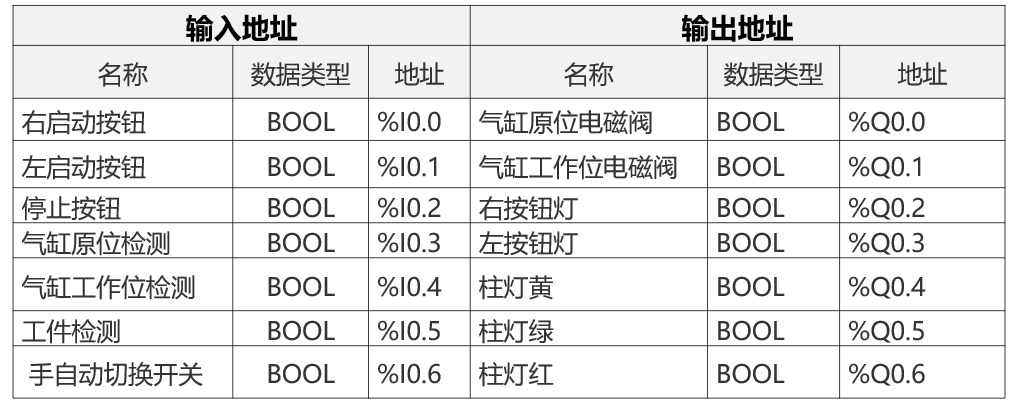
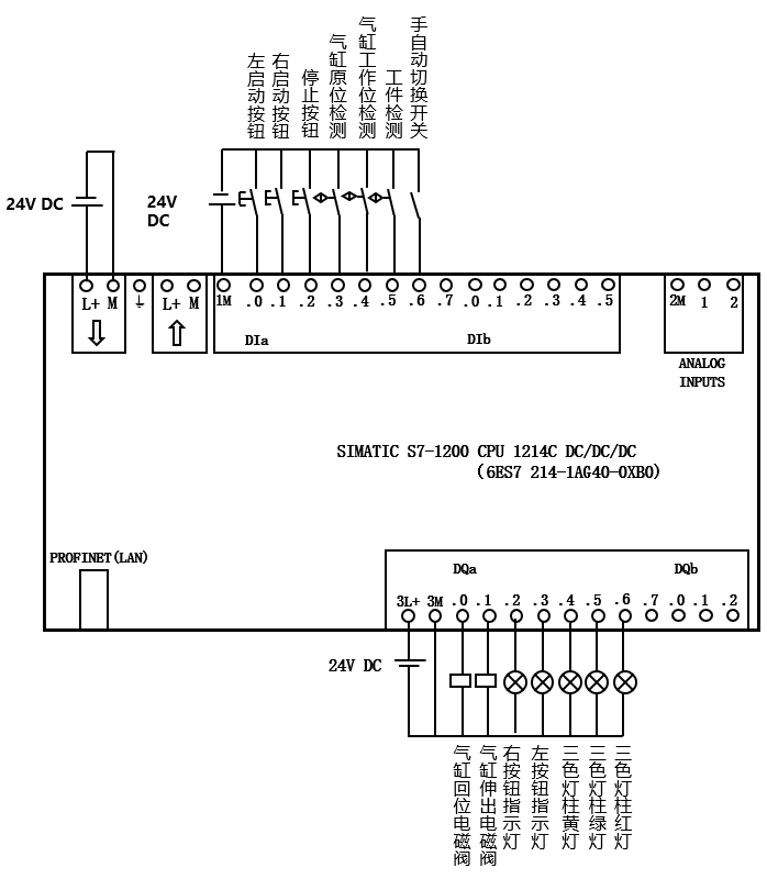
IO address and wiring diagram:This case requires the use of 7 input point addresses and 7 output addresses. The CPU model selected for this case is the CPU1214C PLC, with address allocation as shown in the diagram below:
4
Reference Program
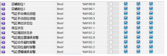
Writing PLC variable table and DB block data:In the PLC variable table, establish some M memory variables to be used as intermediate variables (DB block variables can also be used instead of M memory variables).
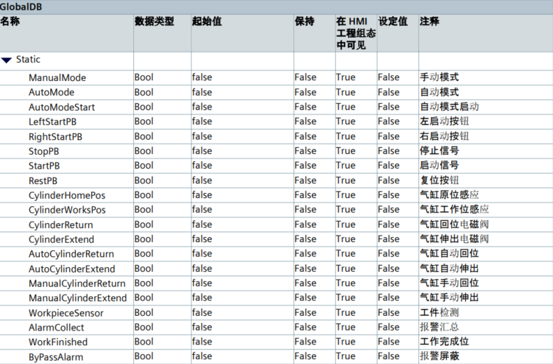
Create a global data block and name it GlobalDB, then define relevant variables in this DB block for subsequent IO mapping.
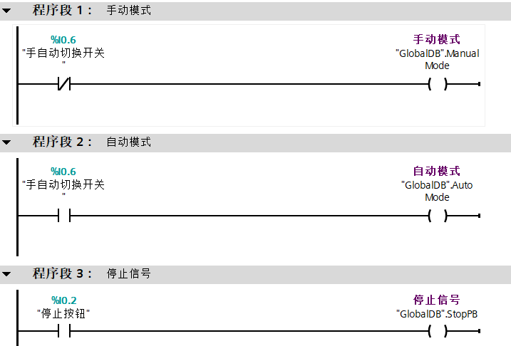
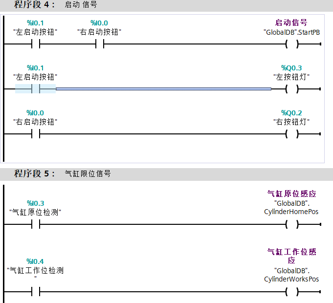
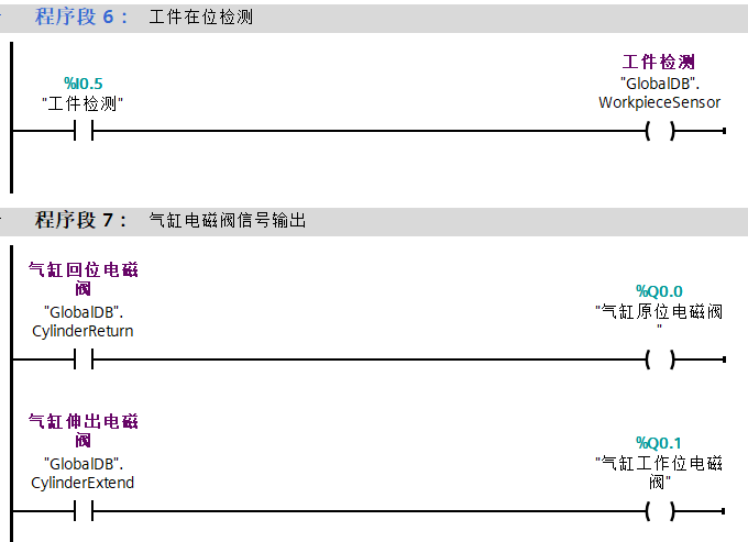
I/O mapping program:Create a new FC1 program block to implement the IO mapping program, associating input and output point addresses with DB block addresses for easier management of addresses. The program is as follows:
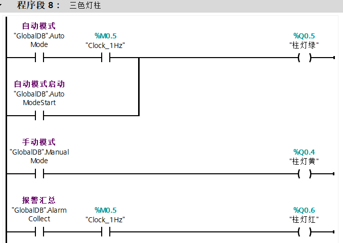
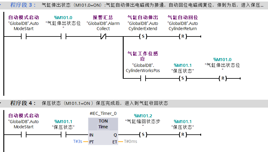
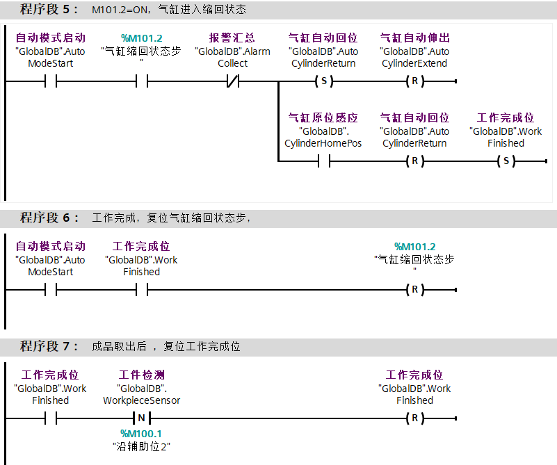
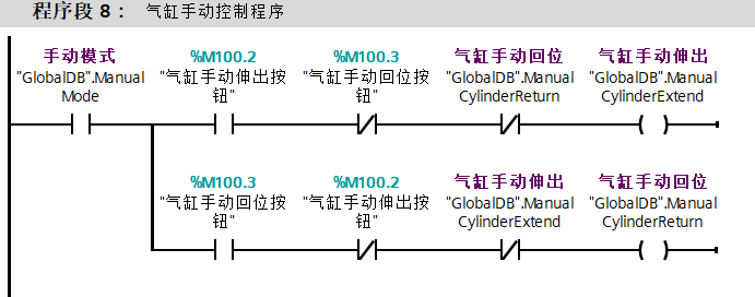
Cylinder action control program:Create a new FB1 program block to control the cylinder, including the action program for the cylinder in automatic mode and the action program for the cylinder in manual mode. The program is as follows:
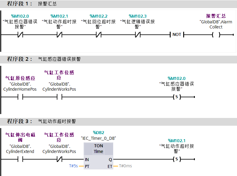
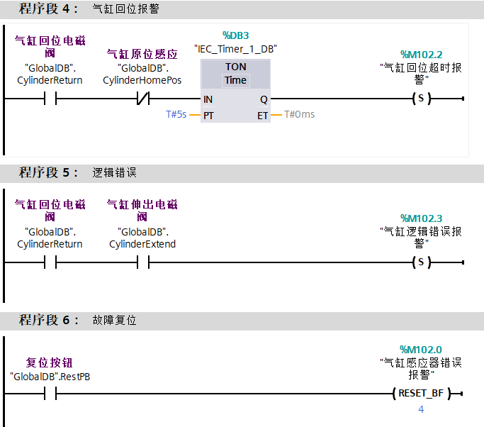
Device alarm program:Create a new FC2 program block to implement the device alarm display. The alarm program includes alarms for abnormal sensor switches of the cylinder, alarms for the extension and retraction of the cylinder, and alarms for control program logic errors. The program is as follows:
Program block calls:All FB blocks or FC blocks must be called in OB1; otherwise, the PLC will not scan and execute the programs inside the FB blocks and FC blocks.
 Scan the QR code to obtain materials related to the case in this article and previous electrical learning materials and manuals.
 Scan the QR code to add the author’s WeChat ID: z971946769 for industrial control technology exchange and learning.
 Click below for the original text for more content!