


This article mainly introduces the usage of the arbitrary waveform output board based on RTUBOX-206. The arbitrary waveform output board converts simulation data from CSV files into analog signals and outputs them to the oscilloscope terminal. The main operation steps consist of 2 steps: (1) Generate arbitrary waveform simulation files (*.csv files) through MATLAB simulation; (2) Use our company’s RtuReplay software to convert the data and output the analog signals, ultimately achieving arbitrary waveform conversion output.
To obtain arbitrary waveform data, we first generate the desired ideal waveform through the MATLAB simulation model and export the simulation data in CSV format.
(1) Find the corresponding version of the software model:
Open the folder <;Store Data as CSV>, where there are already module programs for MATLAB 2022b and MATLAB 2016b versions. If using the 2016b version, change the file extension by removing the suffix .r2016b and modifying the filename.

(2) Select MATLAB model:
The current MATLAB version installed on the computer is 2016b. Change the untitled1.slx.r2016b file to an .slx file, here it is changed to untitled2.slx, as shown below:

Double-click to open the MATLAB file, the result is as shown below:
To simulate the relationship between photovoltaic cell characteristics with illumination and temperature, the fill factor needs to be adjusted, setting the relevant working environment to meet experimental requirements.

(3) Modify the MATLAB model to generate ideal simulation waveforms and export them as CSV files:
Delete the TCP Tx module, which is not used in this project, and modify the input waveform module as shown in the following figure. This example is relatively simple, and specific waveforms can be modified arbitrarily according to actual requirements.

After completing the editing of your waveform, simulate it, and a data.csv file will be generated in the data directory.

When editing MATLAB simulations, please pay attention to the following two points:
1) Sampling frequency: If the sampling frequency is too high and the number of channels is too many, some sampling points may be missing, resulting in incomplete waveforms. Appropriately reduce the frequency or the number of channels to ensure the integrity of the waveform (for example, 10kHz, 4-channel sampling).
2) Sampling time should not be too long. The current board has limited storage memory, and the size of the sampling file should not exceed 45M. Otherwise, the waveform will be incorrect after download (currently, the maximum supported sampling frequency is generally set to 10kHz, 8 channels, and 40 seconds; other sampling frequencies, channel numbers, and sampling times can be calculated accordingly).
3) If an error is reported during MATLAB compilation, it indicates that the data.csv file is open. You need to close the data file before compiling again.

(4) Waveform data analysis:
Open the data.csv file, as shown below. The first column is the sampled time, and the following columns are the waveform coordinates. The current file displays 8-channel data (the software only supports the first column as time and the following columns as waveform data formats).

(5) Introduction to RTUBOX-206 MATLAB DAC hardware

1) The power interface mainly serves the power supply, and this board is mainly installed in the corresponding slot of the RTU206 module chassis.
2) Status lights, numbered from left to right: a, b, c, d.
-
Network light: The network cable is connected normally, and the program runs normally, the network light flashes;
-
Running light: When there is data output, the running light is always on;
-
Download light: When downloading the CSV file to the board, the download light flashes;
-
Power light: The power light is always on after the RTUBOX-206 MATLAB DAC is powered on;
3) The network interface transmits files and operation commands.
4) DAC output interface, connected to the oscilloscope via SMA cable, to observe the waveform output of each channel.
5) Core board.
(6) RTUBOX-206 MATLAB DAC software and hardware network connection
1) After powering on, connect the network cable interface. You can observe that the indicator light 4 is steady and indicator light 1 is flashing;
2) The local address of the current board is: 192.168.0.10. Change the PC IP address to the same subnet, such as 192.168.0.66;
(7) Download and burn waveform files:
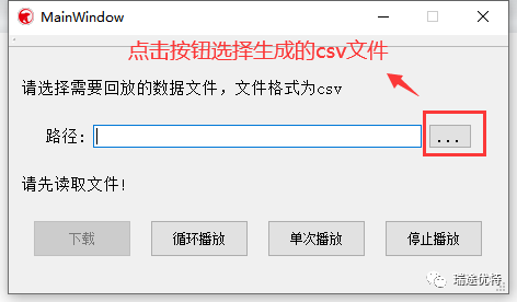
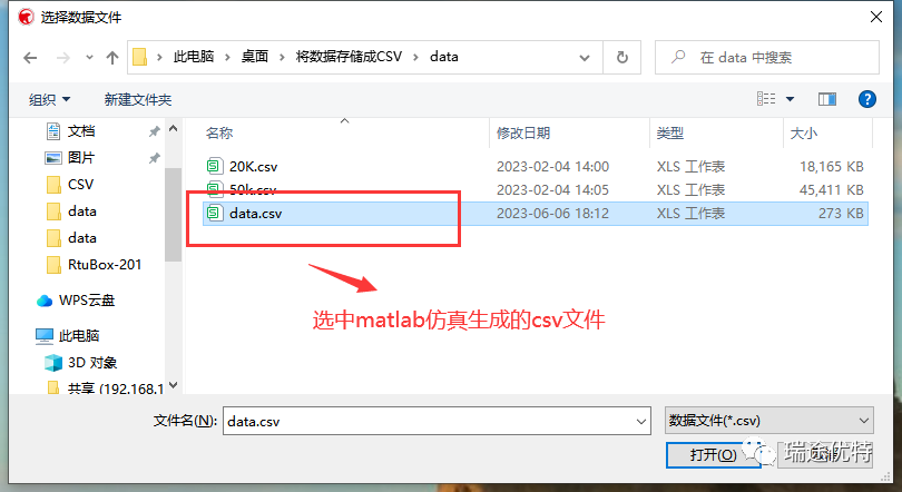
1) Open the release folder, find the RtuReplay.exe software, double-click to open, and the interface as shown in the figure appears:
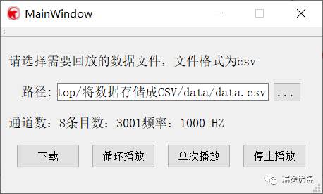
2) Click download to burn the waveform file data to the board’s memory. The download light flashes:
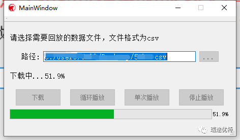
Wait for the file download to complete, at this moment all buttons are non-operational (please be patient and do not close)
3) Waveform display:
-
After the download is complete, click loop playback to observe the waveform loop playback, the running light is always on.
-
Click single playback, the oscilloscope will play once the simulated waveform, and after completion, there is no signal output, the running light goes out.
-
When the signal is output, click stop playback, the running light goes out, and the oscilloscope has no signal output.

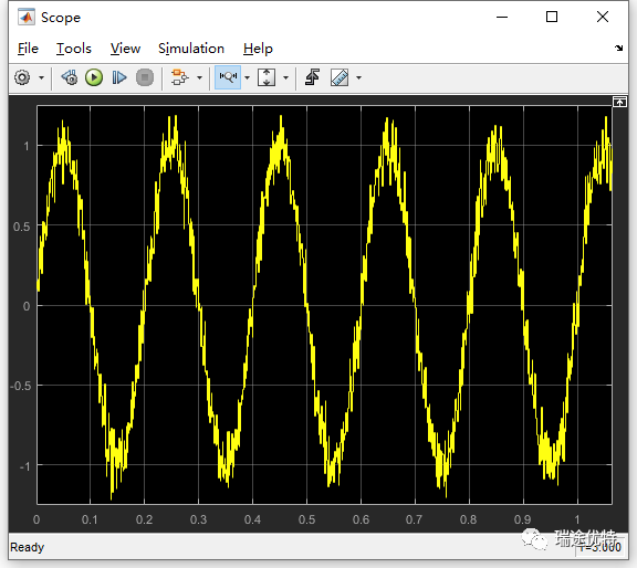
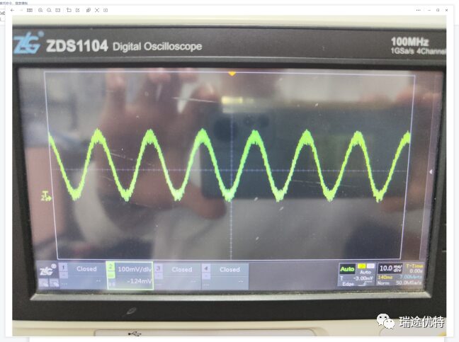
Comparison of MATLAB simulation waveform and oscilloscope waveform is shown below:

Nanjing Ruitu Youte Information Technology Co., Ltd. was established in 2016 and is a national high-tech enterprise focusing on graphical programmable control, motor drive control, power electronics, industrial automation, and other related technology fields. Ruitu Youte launched the first domestically developed real-time digital controller RTU-BOX in 2018, supporting both SIMULINK model and C language development modes. Its rich hardware resources, iteratively improved system performance, software that conforms to the usage habits of Chinese users, and comprehensive localized services have received increasing recognition and support from users. The company also has several product series including the RTM series modular power electronics power modules, RT series integrated drivers, RTP series high power density power supplies, and can provide a complete set of solutions and related supporting services based on these products.

Photovoltaic Cell Simulation Source
Technical Department Mei Qixian
Introduction to RTU-BOX205 Controller DAC/ADC Usage
Technical Department Hao Jian

Steps to Set Flash Writing for TMS320C28346CCS9.1.0
Technical Department Gu Jie
