Getting Started with Arduino Input/Output: A Beginner’s Guide
This article introducesthe implementation of basic input/output on Arduino, detailing how to use switches for digital input and potentiometers for analog input. The article provides a list of required materials and detailed circuit connection steps, while explaining the working principles of the code and key functions.
Arduino is one of the widely used development solutions for both beginners and professionals. By mastering basic inputs and outputs, you can build more functionalities, perform more operations, and realize more different designs. Programming on Arduino can stimulate innovative thinking, allowing you to complete more complex projects step by step and explore infinite possibilities. The following video will introduce how to use switches for digital input and variable resistors for analog input. Hurry up and click to watch!
Once you have mastered the basics of Arduino and can control an LED with code, it is time to learn about Arduino inputs, which are the electrical signals used to provide information to the Arduino development board. The Arduino evaluation board can be programmed to receive electrical signals and take corresponding actions based on those inputs.
A switch is a mechanical device that typically uses a lever or button to connect or disconnect a circuit. To build this circuit, you will need a small button, which is one of many different types of switches.It is recommended to use an Arduino Uno (1050-1024-ND), or a compatible development board such as Adafruit Metro (1528-1214-ND), Sparkfun Redboard (1568-1977-ND), or Seeeduino (102010026-ND) to get started.To learn how to build the circuit in this issue, please prepare the following materials:
Arduino Unoor a compatible development board, along with a USB cable
Breadboard without soldering
Jumper wiresorsingle-core wires
3V through-hole LED
Through-hole resistors, 100-1000 ohms and 10K ohms
Touch switch
Potentiometer
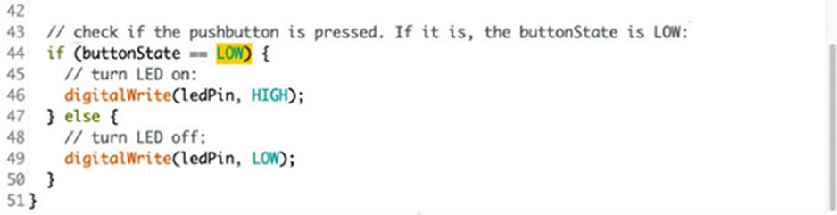
Start with the basic setup for prototyping a new circuit: first assemble the Arduino UNO evaluation board and the breadboard on a fixed evaluation board, connect the 5V and ground from the Arduino evaluation board to the rails on the breadboard, and then connect to the rails on the other side of the breadboard. This is the basic setup for prototyping a new circuit.Next, connect an LED at the output end, connecting the longer positive leg to pin 13, and connecting the negative leg to ground through a small-value resistor (100 ohms – 1K ohms).Next, add the button to the breadboard, which is usually designed to span the center divider of the breadboard. If the button does not fit snugly, you may need to slightly bend its pins.One side of the button connects to pin 2, while the other side connects to ground through a larger resistor (10K ohms).Here, diagonal pins are used instead of other connections because this is a reliable way to ensure correct connections regardless of how the switch is wired internally. You can also use a multimeter to check by probing the two pins on the switch and pressing it to see which ones are connected.Once the circuit is connected, you can plug in the USB cable and upload the new program.Open the downloadable Arduino software, click File > Example > 02.Digital > Button.After uploading the code to the Arduino evaluation board, when the button is pressed, the LED light will turn off from being on.At the beginning of this program, there are some constants that are similar to variables and are used to store information. However, as you know, constants do not change throughout the program, so they are very suitable for storing pin numbers. They occupy less memory space than variables.Line 36 configures pin 2 as an input mode, allowing it to receive the state of the buttonIn the main loop, the digitalRead() function checks the state of pin 2, which can be 5 volts (i.e., HIGH) or ground (i.e., LOW), and stores that state in a variable called buttonStateLine 44 contains an if() statement, which uses comparison operators to perform conditional judgment, such as greater than, less than, or in this case, equal to, indicated by two equal signs. If the condition is met, the code inside the braces will be executed, and the LED light will turn on (HIGH). If the condition is not met, the code inside the else statement will be executed, and the LED light will turn off (LOW).In a stationary state, there is no connection between the switch’s pins. Pin 2 is connected to 5 volts through a larger resistor of 10K ohms. When the button is pressed, the switch leads are connected, and pin 2 is grounded without a resistor. Since the current will take the path of least resistance, the pin will strongly sense the connection to ground and ignore the weaker connection with the 10K ohm resistor and 5 volts. But when there is no other signal, such as when the switch is not pressed, the pin can only sense the weaker connection to the 5 volts.Therefore, this resistor pulls the pin up to 5 volts, which is why it is called a pull-up resistor. If there is no pull-up resistor connected, pin 2 will not connect anywhere before the button is pressed, which is called a floating pin, and may produce random noise from static electricity and electromagnetic interference.Similarly, resistors can also be used to connect a pin to ground, which is called a pull-down resistor. Then, you can connect the other side of the button to power instead of ground.So, to change the function of the button, you can do it either by changing the wiring of the circuit or changing the code, but never do both at the same time! In this case, the latter is more convenient, but not always so.Next, edit the if() statement and its comments on lines 43 and 44, change HIGH to LOW, and then upload the updated code to the development board to check if the button can now turn on the LED light instead of turning it off.Many of the pins on Arduino have built-in pull-up resistors, which are designed for this purpose, and can be enabled in the setup so that no extra resistors are needed on the breadboard.You can also use the serial monitor, which is a way to check different position information in the code by reporting to the computer via the USB cable. To understand how it works, go to File> Examples> 01 Basics> DigitalReadSerial in the Arduino software, and then upload the example program to your Arduino.To establish a serial connection, you need to use the Serial.begin() function in the setup, where 9600 is the baud rate, indicating the number of data bits transmitted per second.Within the main program loop, you can use the Serial.print() function to send information to the serial port. Serial.println() works similarly to Serial.print(), but will print on a new line.Line 27 in the code adds the current button state value to the serial port.So, when the serial monitor is open, you can see in real-time the values detected by Arduino on pin 2. The serial monitor is very useful for troubleshooting, allowing you to easily compare expected results with what Arduino is actually doing.You can also use serial communication for more functions, such as communication between devices. For more details, please refer to the Arduino reference documentation.Next, we will use analog input to send information to the Arduino board. These pins starting with A, which are located opposite the digital input/output pins, connect to Arduino’s analog-to-digital converter (ADC). It can convert analog signals ranging from 0 volts to 5 volts into a digital range from 0 to 1023.To create this analog signal, you can use a variable resistor, which changes its resistance value when acted upon. For example, you can turn the knob on a potentiometer, press or bend a force-sensitive resistor (FSR), or change the exposure of a light-dependent resistor.Insert a small potentiometer into three rows of the breadboard, connecting the outer pins to power and ground, and the middle pin to the analog pin A0.Connect an LED to pin 9 so that you can control the brightness of the LED using pulse-width modulation (PWM).The built-in example code for this circuit can be found in Arduino software under 03 Analog> AnalogInOutSerial.After uploading the code, open the serial monitor and observe the state of the LED light when turning the knob on the potentiometer. The value read from the analog input will be in the first column, and the brightness value of the LED will be in the second column.This example program uses the map() function on line 39, which maps a range of numbers to another range. It has five parameters, including: the value to be changed, the lower limit of the current range, the upper limit of the current range, the lower limit of the target range, and the upper limit of the target range. Thus, this line of code sets a variable named outputValue to a number between 0 and 255, depending on the position of the potentiometer.Lines 44 to 47 of the serial print commands list text labels (the content within quotes), as well as the values input from the sensor and output to the LED.By simultaneously viewing these values on the serial monitor, you can better understand how functions like map() work. Keep this in mind when writing your own code!Many sensors work similarly to digital switches or analog inputs, so you can use the same code just explained. For example, you can replace the button with an infrared sensor, or replace the potentiometer with a light-dependent resistor.If you have watched the introduction from the previous issue and have made it this far, then you have now mastered most of the basic building blocks of Arduino programs. When designing your projects, ask yourself what the inputs and outputs are, and whether they are analog or digital. Then you can mix and match the built-in examples accordingly and start your prototyping. Arduino has many more built-in examples for you to explore slowly, unleash your creativity, and achieve more creative births.
Do you like Digi-Key’s articles? Go to the Digi-Key website now, or follow Digi-Key’s official WeChat digikey_electronics!
· END ·
Welcome to bookmark us as “Starred“, so you can receive push messages first.
Scan to follow: Automotive Development Circle, reply “Auto“
Get a free Autosar introduction and practice material package!
Scan to add the assistant and reply “join group”
Face-to-face communication with electronic engineers