Wireless technology is ubiquitous. The number of new wireless devices that can connect wirelessly is increasing, and their data consumption is growing day by day. The number of wireless devices and data consumption is increasing exponentially every year. To meet such demands, many organizations are researching new wireless technologies to improve existing wireless architectures. To achieve this goal, wireless standardization organizations around the world have embarked on a daunting task of defining the next generation of wireless network systems, known as 5G. The three major application scenarios of 5G networks include: Enhanced Mobile Broadband (eMBB), Massive Machine Type Communication (mMTC), and Ultra-Reliable Low-Latency Communication (uRLLC).
The above three application scenarios can be used to meet different needs. For example, eMBB focuses on peak data transmission rates, while uRLLC emphasizes reducing latency. Due to the diverse demands, a single specific technology cannot meet all needs, so 5G will be a combination of various new technologies. Especially for the eMBB application scenario, researchers need to increase the peak data transmission rate to over 100 times that of 4G networks, while the available spectrum below 6 GHz is already extremely limited. It has been proven in practice that data rates are directly related to available spectrum, and according to Shannon’s theorem, capacity is a function of bandwidth (i.e., spectrum) and channel noise. Because the spectrum below 6 GHz is almost fully allocated, researchers must turn to spectrum above 6 GHz to study the field of millimeter waves.
Service providers around the world have spent billions of dollars on spectrum to serve customers. The high auction prices for spectrum below 6 GHz highlight the intense competition in the market and the scarcity of precious resources. As mentioned earlier, according to Shannon’s theorem, both data transmission rates and capacity improvements are limited by spectrum. The wider the spectrum range, the higher the data transmission rate, allowing service providers to serve more users and provide a more consistent mobile broadband data transmission experience. Millimeter wave spectrum is not only abundant but can also be used with minimal authorization, enabling operators worldwide to utilize millimeter waves. The challenges faced in adopting mmWave mainly lie in the fact that this spectrum still has many unknowns, has not been fully studied, and has unresolved technical issues.
To leverage millimeter waves for 5G networks, researchers must develop new technologies, algorithms, and communication protocols, as the fundamental properties of millimeter wave channels are vastly different from current cellular models and are relatively unknown. The importance of establishing millimeter wave prototypes cannot be overstated, especially given the urgent timeline. Establishing a millimeter wave system prototype can demonstrate the feasibility of a technology or concept, something that simulation cannot achieve. Millimeter wave prototypes can conduct wireless real-time communication in various scenarios, helping to unveil the mysteries of millimeter wave channels and promoting the application and popularity of the technology.

Figure 1: Three Advanced 5G Application Scenarios Defined by 3GPP and IMT 2020
To achieve this project goal, NI launched the world’s first real-time millimeter wave prototype validation system designed to help engineers and researchers quickly validate millimeter wave systems. The NI millimeter wave transceiver system combines flexible modular hardware with powerful application software, making it suitable for millimeter wave applications in SDR. As the millimeter wave transceiver is a complete SDR, both the hardware and software have full functionality and modular characteristics, allowing researchers to quickly deploy their designs and use software for rapid iteration and optimization.
Creating a complete mmWave communication prototype presents various challenges. Assume there is a baseband subsystem capable of handling several GHz channels. Currently, most LTE implementations use 10 MHz channels (up to 20 MHz), and the computational load increases linearly with bandwidth. In other words, computational power must increase by a factor of 100 or more to meet the 5G data rate requirements. The algorithms used in LTE turbo decoders not only require a large amount of computational resources but also require high-performance computing software to process data in real time. FPGA provides an ideal hardware solution for these computations, and FPGA is indispensable for ultra-wideband turbo decoding.
Although FPGA is the core component of the millimeter wave prototype validation system, designing a multi-FPGA system capable of handling several GHz channels will complicate the system further. To address system complexity and software challenges, NI provides the source code for the millimeter wave physical layer, covering the basic principles of millimeter wave system baseband, and abstracts the process of moving and processing data between multiple FPGAs, thereby simplifying the workload.
FPGA is only part of the millimeter wave prototype validation system. Data must be able to move between the digital domain for processing and also needs to move between the analog domain for signal transmission and reception. The development of DAC and ADC technologies has made it possible to capture signals from 1 to 2 GHz. There are millimeter wave frequency ICs available on the market. These ICs can connect to the ADC and DAC of the millimeter wave transceiver system for evaluation and then perform prototype validation work. However, RFIC cannot provide the high power output or RF quality needed for channel probing or communication prototype validation. To integrate higher power and better RF quality, signals need to be upconverted to 12 GHz through the IF stage. Finally, the millimeter wave radio station connects to the IF module. If starting from scratch, developing each part of the prototype validation system requires various design expertise and a large amount of engineering resources. Each part’s hardware design is not easy, and there is also a need to develop software for controlling and synchronizing hardware at various stages, further increasing the complexity of custom designs. The millimeter wave transceiver system provides a complete prototype validation solution that helps engineers transition more quickly from concept and algorithm design to prototype validation.
NI offers four ready-to-use millimeter wave prototype validation system configurations, which will be detailed below. The millimeter wave transceiver system is based on the PXIe platform and includes a baseband processing subsystem with 2 GHz bandwidth, an IF stage with 2 GHz bandwidth, and a modular millimeter wave radio station located outside the chassis. The system block diagram is shown in Figure 2.
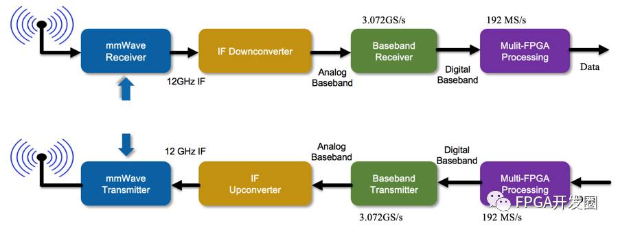
Figure 2: Millimeter Wave System Block Diagram
The modular approach allows for flexible hardware platforms that can meet various channel and configuration needs by adding or removing modules. Users can choose to use the complete NI millimeter wave solution or integrate their RF devices into the NI IF or baseband systems. Users can also use the same system and the same IF and baseband hardware and software to develop prototypes across different frequency bands. This system can also scale from a unidirectional SISO system to a bidirectional MIMO system, making it suitable not only for channel probing but also for parallel transmission and reception to achieve complete two-way communication links. We will further introduce various system components and configurations. This document does not discuss software for specific applications.
The millimeter wave transceiver system is an SDR platform suitable for building millimeter wave applications and includes system prototype validation. This system provides users with a flexible hardware platform and application software to conduct real-time wireless millimeter wave communication research. The software is open to users and can be adjusted according to research needs, allowing designs to be iterated and optimized repeatedly to meet specific goals or purposes.
The NI millimeter wave transceiver system includes a PXIe chassis, controller, clock distribution module, FlexRIO FPGA module, high-speed DAC and ADC, LO and IF modules, and millimeter wave radio station. These modules can be assembled into different configurations to meet the needs of various millimeter wave applications, such as channel probing, MIMO communication link prototype validation, etc. This article details the hardware used in the millimeter wave transceiver system and the interactions between the modules. For detailed performance specifications, please refer to the millimeter wave transceiver system data sheet.
PXI Express Chassis The prototype validation system is based on the PXIe-1085 chassis. The chassis contains various processing modules and provides power, interconnection functions, and timing and synchronization infrastructure. This 18-slot chassis features PCI Express (PCIe) 3rd generation technology in each slot, suitable for high throughput and low latency applications. The chassis can provide 4 GB/s single-slot bandwidth and 24 GB/s system bandwidth. The PXIe-1085 adopts a dual-switch backplane architecture, as shown in Figure 3 system diagram. Due to the flexible PXI design, multiple chassis can be connected together in a daisy chain or star configuration when creating high-channel-count systems.
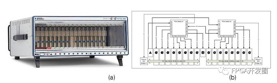
Figure 3: 18-slot PXIe-1085 Chassis (a) and System Diagram (b)
High-Performance Reconfigurable FPGA Processing Module All SDRs require software and computational components to form the physical layer. This millimeter wave prototype validation system uses a single-slot FlexRIO module to add a flexible high-performance processing module to the PXIe chassis, which can be programmed using LabVIEW. The PXIe-7976R FlexRIO FPGA module can run independently and provides a customizable large Xilinx Kintex-7 410T, connected to the PXI Express backplane via PCI Express Generation 2 x8. This millimeter wave transceiver system can assign different processing tasks to different FPGAs based on different configurations, which can be set through software.
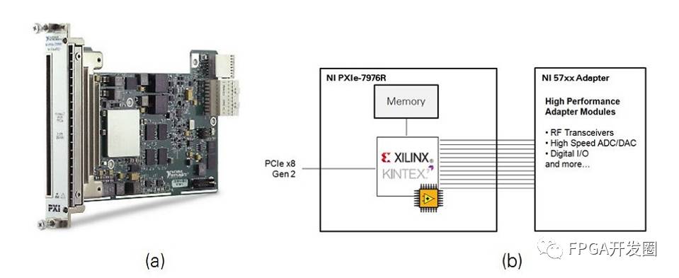
Figure 4: PXIe-7976R FlexRIO Module (a) and System Block Diagram (b)
High-Throughput Applications with High-Performance FPGA The NI PXIe-7902 FPGA module is a powerful processing module built on the Xilinx Virtex 7 485T. The large FPGA is suitable for processing compute-intensive applications such as millimeter wave physical layers. This module can transfer data between the PXIe chassis backplane at PCIe gen 2×8 speeds. For applications requiring faster data transfer rates, the PXIe-7902 also offers six miniSAS HD front panel connectors composed of 24 GB-level transceivers (MGT). MGT can connect to other PXIe-7902 or other DAC/ADC modules, allowing multi-channel baseband signals with real-time bandwidth of up to 2 GHz.
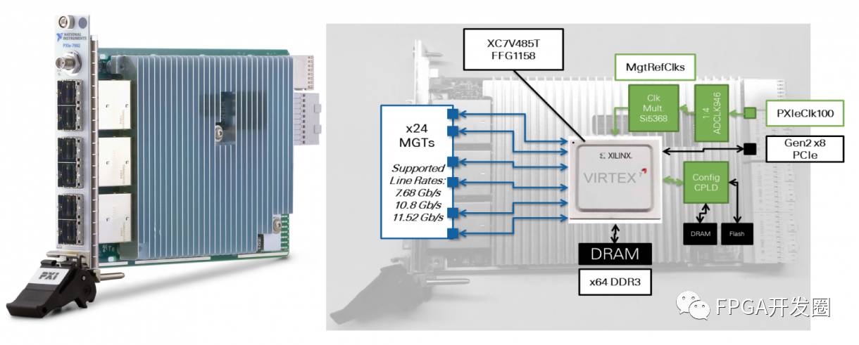
Figure 5: PXIe-7902R FPGA Module (a) and System Block Diagram (b)
Ultra-Wideband DAC and ADC Figure 6 is the PXIe-3610 DAC, and Figure 7 is the PXIe-3630 ADC. Both can connect to analog baseband differential I/Q pairs via four MCX front panel connectors. These modules can connect to form a baseband loopback testing system and connect to the PXIe-3620 IF module or third-party baseband hardware. Table 1 provides basic performance information. For detailed performance information, please refer to the millimeter wave transceiver system data sheet.
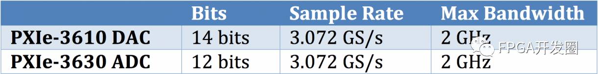
Table 1: Basic Performance Specifications of PXIe-3610 and PXIe-3630

Figure 6: DAC Module and Program Block Diagram
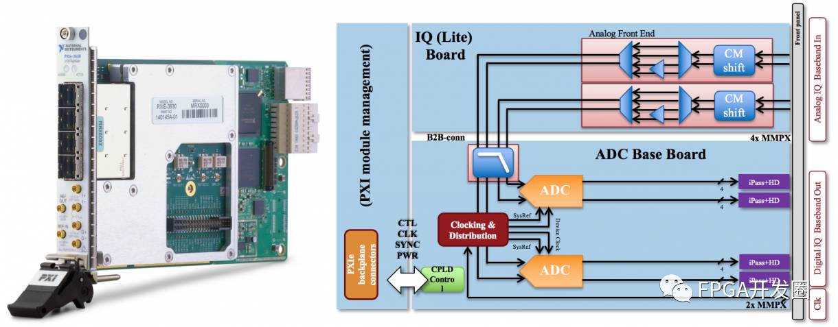
Figure 7: ADC Module and Program Block Diagram
12 GHz IF Module The PXIe-3620 LO/IF module can handle a set of transmission chains and a set of receiving chains with bandwidths of up to 2 GHz each. The NI PXIe-3620 can upconvert baseband signals to software-programmable IF between 10.5 to 12 GHz by combining input signals with an integrated LO. For the receiving part, the NI PXIe-3620 can receive input IF from 10.5 to 12 GHz and convert it to baseband signals. This module features internal gain control and can transmit signals of up to 7 dBm and receive signals of 20 dBm. The PXIe-3620 also provides LO reference signals for the NI 3647 and NI 3657 millimeter wave stations. The LO/IF module can accept external LO signals and can drive LO signals for other IF modules to synchronize multiple transmitter/receiver data streams in MIMO topologies. Differential I/Q can be accessed via the MXC connector on the device front panel.
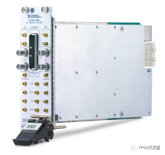
Figure 8: PXIe-3620 IF Module
Millimeter Wave Station The NI 3647 and NI 3657 modular transmit and receive radio stations provide high-quality RF signals for the NI millimeter wave transceiver system. The NI 3647 millimeter wave transmitter operates in the frequency range of 71 – 76 GHz; with output power up to 25 dBm * and a bandwidth of up to 2 GHz RF. This transmitter can be paired with the NI 3657 millimeter wave receiver operating at 71 – 76 GHz. Both devices feature WR-12 waveguide ports for connection to user-provided antennas, such as horn antennas or phased array antennas. The NI 3647 transmitter can act as a frequency multiplier for upconversion operations. The attenuators and amplifiers included in the radio station can be used to maximize gain control and reduce noise figure. For detailed RF specifications of the millimeter wave transceiver system, please refer to the product data sheet.
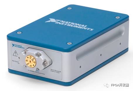
Figure 9: Millimeter Wave Radio Station from 71 to 76 GHz
* The 25 dBm output power version is not available in some regions. The globally available version is 20 dBm output power.
The NI millimeter wave transceiver system is a flexible hardware platform capable of meeting various communication needs. In addition to creating various systems by adding or removing system hardware, the platform also provides four basic configurations for the most common application scenarios:
-
Unidirectional SISO
-
Unidirectional 2×2 MIMO
-
Bidirectional SISO
-
Bidirectional 2×2 MIMO
Unidirectional Systems The two unidirectional systems mentioned above consist of two PXIe chassis, one equipped with a transmitter and the other with a receiver. This configuration is very suitable for channel probing measurements. In this configuration, users can separate the transmitter and receiver subsystems and perform channel probing measurements in various environments. Due to the modular nature of the PXIe architecture system, users can easily add additional hardware to meet different research needs, such as increasing the channel count to enhance the accuracy of angle of arrival measurements. In addition to increasing the number of receiving channels for parallel reception or simultaneous transmission and reception, users can also add external switches to the SISO system. This flexibility allows researchers to choose the hardware configuration that best meets their measurement speed and configuration needs. Because the millimeter wave transceiver system is designed for MIMO architecture, it is easy for each channel to share the LO signal for phase coherence. Figures 10 and 11 are the system program block diagrams for SISO and 2×2 MIMO.
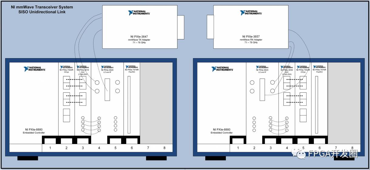
Figure 10: Unidirectional SISO Configuration
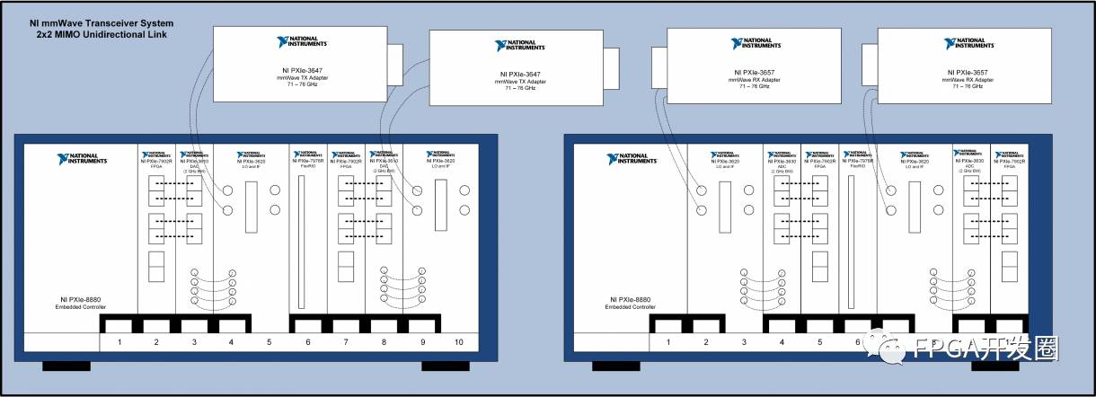
Figure 11: Unidirectional MIMO Configuration
Bidirectional Systems The two bidirectional system configurations each include two PXIe chassis, one equipped with a transmitter and the other equipped with a receiver. These systems are designed for communication prototype validation, providing researchers with the necessary hardware to create real-time bidirectional communication links. There are still many unknowns in millimeter wave communication research. It is essential to determine the signal behavior within the millimeter wave channel. While a fully defined channel model is very helpful for algorithm developers, real-time communication links ultimately need to be prototype validated to determine their performance in new frequency bands. Whether validating new physical layers and wireless interfaces or understanding how existing LTE physical layers can adapt to ultra-wide bandwidths like 2 GHz, the NI millimeter wave system can be used to verify its performance in real-time. Combining the NI millimeter wave system, FPGA processing capabilities, and LabVIEW, it becomes possible to perform real-time modulation, demodulation, coding, and turbo decoding at 2 GHz bandwidth. These systems can serve as platforms for researchers to develop and test communication protocols. Unlike communication in frequencies below 6 GHz, millimeter wave signals have high directionality, so protocols must ensure that two or more nodes can locate each other. Nodes must be able to exchange control and measurement information, such as beam control or random access protocols. Figures 11 and 12 are configuration diagrams for the two bidirectional systems.
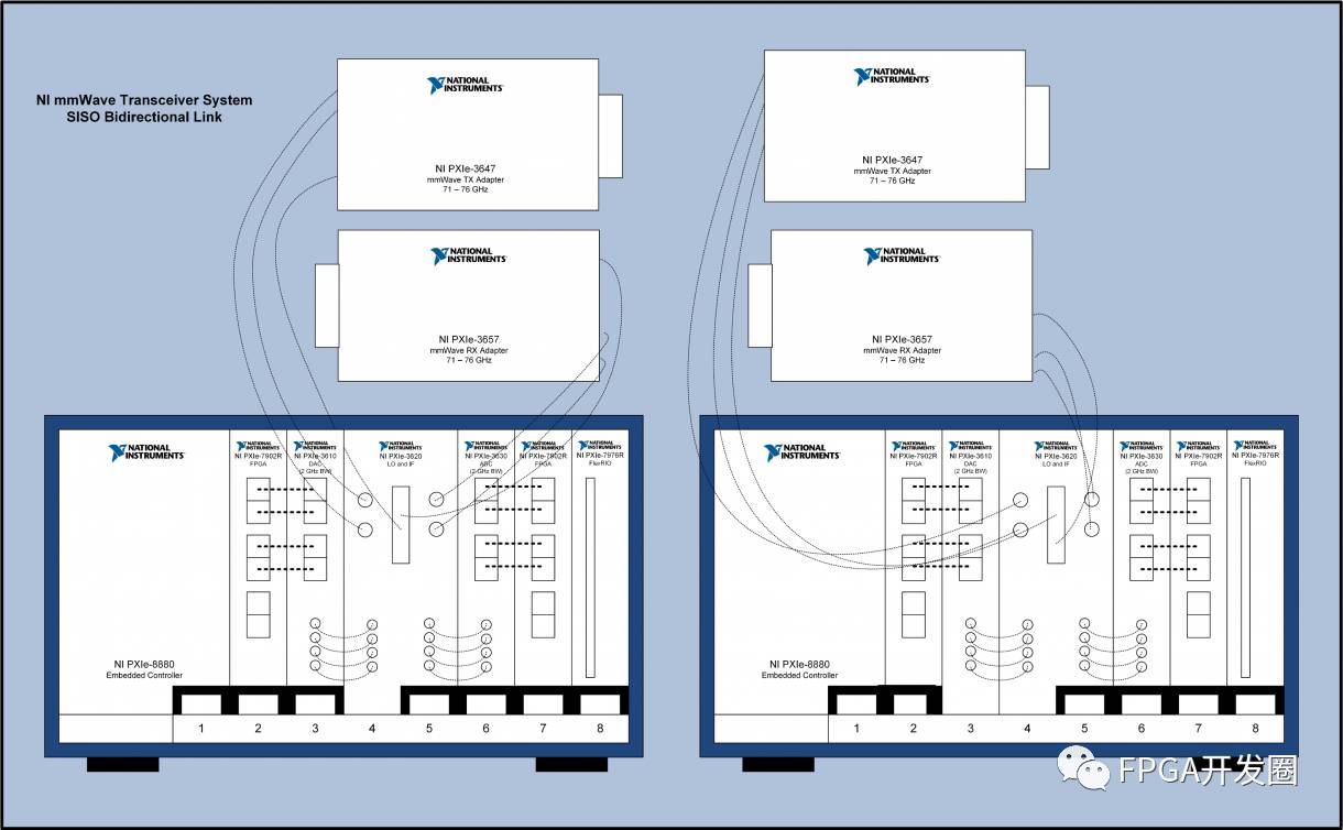
Figure 12: Unidirectional SISO Configuration
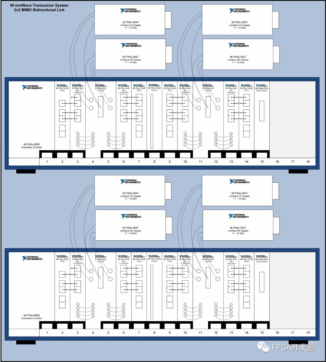
Figure 13: Unidirectional MIMO Configuration
The NI millimeter wave transceiver system is a combination of a series of modular hardware suitable for channel probing, real-time bidirectional communication system prototype validation, and various other applications. This system is based on the PXI platform and offers flexible modular combinations, providing various configurations to meet the ever-changing research needs. The millimeter wave radio station itself has modular characteristics and can be replaced with other RF front ends, allowing for the study of various frequencies while using the same hardware and software combination, thus saving engineering design time and greatly enhancing system reusability. This hardware, combined with the powerful capabilities of LabVIEW, provides an excellent platform for millimeter wave communication prototype validation and helps engineers innovate more quickly.
4:1 Lossless Compressed Video? How is it done?
Old Antiques vs. New Technology! Amazing Information Found After Disassembling the Phantom v5 Camera from 2001
Xilinx Widely Deploys Dynamic Reconfiguration Technology
More Functional Modules Seamlessly Connected: PXIe700 Board Expands Functions via FMC HPC
[Video] PureLifi: A Wireless Communication Implemented Through LED Lights
Ultra-Low Latency of 2.5 Microseconds! TrustNode Board-Level SDN Router Hits the Market
[Download] UltraFast Design Method Quick Reference Guide (UG1231)
Professional RF Learning Module: ADALM-PLUTO SDR USB Learning Module Based on Zynq SoC
Xilinx Spartan-7 Finally Available for Order!
Lynx Product: Kernel Separation Technology LynxSecure Based on Xilinx Zynq UltraScale+ MPSoC
[Video] Implementing Single-Chip 4K Video Codec Processing on Zynq MPSoC
36 Years of Innovation: How Vicor Continues to Break Power Density Records?
1/64 Pixel Completion of Composite Surface Profile Extraction: LineCam3D Laser Industrial Camera (from VRmagic)
[Video]: Debugging After Compilation Using Incremental Compilation Process
