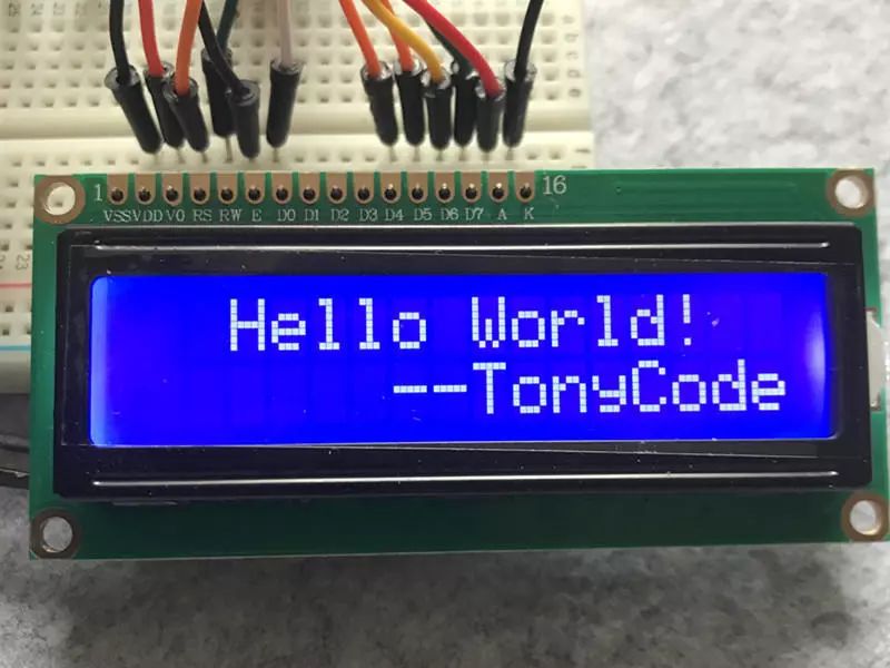
The LCD1602, also known as the 1602 character LCD, is a dot matrix liquid crystal module specifically designed to display letters, numbers, and symbols. It can display 16×2 characters, totaling 32 characters. In this article, we will explore the LCD1602 and drive it to display “Hello World”.
1. Introduction to LCD1602
For microcontroller enthusiasts and electronics hobbyists, the liquid crystal display module is a common component used. These modules consist of several dot matrix character positions and can be categorized as 1602, 12864, etc., based on the content displayed. The LCD1602 can display two lines of characters, with 16 characters per line, and it comes in different background colors, such as blue with white text and yellow with white text.
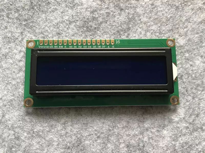
LCD1602 Interface Description:
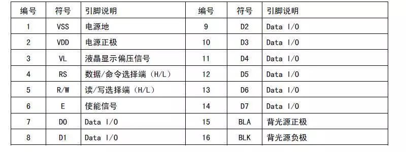
Where:
-
VL(V0): Liquid crystal contrast adjustment pin, used to adjust the display contrast, generally connected to a 10K potentiometer for adjustment.
-
RS: Data/command selection. High level indicates data, low level indicates command.
-
RW: Read/write selection. High level is read, low level is write. Generally, we write data for display, so this pin is grounded.
-
EN: Enable signal, used in conjunction with data/command read/write.
-
D0-D7: Bidirectional data pins. You can use 8 data lines for parallel operation or 4 data lines for serial operation.
The driving of the LCD1602 is also very simple. The official data manual provides the basic operation timing and initialization settings. In this article, to reduce the number of connections, we will use a 4-bit serial operation mode, where an 8-bit data and command are written to the 1602 in two parts.
2. Experiment Materials
-
Uno R3 Development Board
-
USB Data Cable
-
Breadboard and Connecting Wires
-
LCD1602 Display
-
16Pin Header
-
10K Potentiometer
3. Experiment Steps
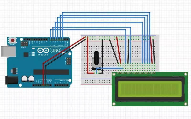
1. Build the circuit according to the schematic diagram.
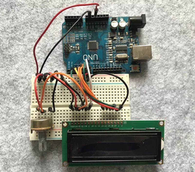
The 1st, 5th, and 16th pins of the LCD1602 are connected to the GND of the development board; the 2nd and 15th pins of the LCD1602 are connected to the 5V of the development board; the 4th, 6th, 11th, 12th, 13th, and 14th pins of the LCD1602 are connected to digital pins 7, 6, 5, 4, 3, and 2 of the development board, respectively; the two ends of the potentiometer are connected to 5V and GND, and the middle pin is connected to the 3rd pin of the LCD1602.
The experimental schematic is shown in the figure below:
The physical connection diagram is shown below:
2. Create a new sketch, copy the code below, replace the auto-generated code, and save it.
int LCD1602_RS = 7;int LCD1602_EN = 6;int DB[4] = { 2, 3, 4, 5};
/* * LCD Write Command */void LCD_Command_Write(int command){  int i, temp;  digitalWrite( LCD1602_RS, LOW);  digitalWrite( LCD1602_EN, LOW);
  temp = command & 0xf0;  for (i = DB[0]; i <= 5; i++)  {    digitalWrite(i, temp & 0x80);    temp <<= 1;  }
  digitalWrite( LCD1602_EN, HIGH);  delayMicroseconds(1);  digitalWrite( LCD1602_EN, LOW);
  temp = (command & 0x0f) << 4;  for (i = DB[0]; i <= 5; i++)  {    digitalWrite(i, temp & 0x80);    temp <<= 1;  }
  digitalWrite( LCD1602_EN, HIGH);  delayMicroseconds(1);  digitalWrite( LCD1602_EN, LOW);}
/* * LCD Write Data */void LCD_Data_Write(int dat){  int i = 0, temp;  digitalWrite( LCD1602_RS, HIGH);  digitalWrite( LCD1602_EN, LOW);
  temp = dat & 0xf0;  for (i = DB[0]; i <= 5; i++)  {    digitalWrite(i, temp & 0x80);    temp <<= 1;  }
  digitalWrite( LCD1602_EN, HIGH);  delayMicroseconds(1);  digitalWrite( LCD1602_EN, LOW);
  temp = (dat & 0x0f) << 4;  for (i = DB[0]; i <= 5; i++)  {    digitalWrite(i, temp & 0x80);    temp <<= 1;  }
  digitalWrite( LCD1602_EN, HIGH);  delayMicroseconds(1);  digitalWrite( LCD1602_EN, LOW);}
/* * LCD Set Cursor Position */void LCD_SET_XY( int x, int y ){  int address;  if (y == 0)    address = 0x80 + x;  else          address = 0xC0 + x;  LCD_Command_Write(address);}
/* * LCD Write a Character */void LCD_Write_Char( int x, int y, int dat){  LCD_SET_XY( x, y );  LCD_Data_Write(dat);}
/* * LCD Write String */void LCD_Write_String(int X, int Y, char *s){  LCD_SET_XY( X, Y );    // Set Address  while (*s)             // Write String  {    LCD_Data_Write(*s);    s ++;  }}
void setup (void){  int i = 0;  for (i = 2; i <= 7; i++)  {    pinMode(i, OUTPUT);  }  delay(100);  LCD_Command_Write(0x28);// Display Mode Setting 4-line 2-row 5x7  delay(50);  LCD_Command_Write(0x06);// Display Cursor Move Setting  delay(50);  LCD_Command_Write(0x0c);// Display On and Cursor Setting  delay(50);  LCD_Command_Write(0x80);// Set Data Address Pointer  delay(50);  LCD_Command_Write(0x01);// Clear Display  delay(50);
}
void loop (void){  LCD_Write_String(2, 0, "Hello World!");  LCD_Write_String(6, 1, "--TonyCode");}
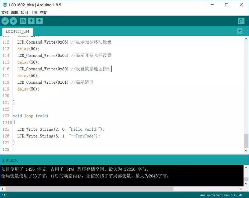
3. Connect the development board, set the corresponding port number and development board type, and download the program.
4. Experimental Phenomenon
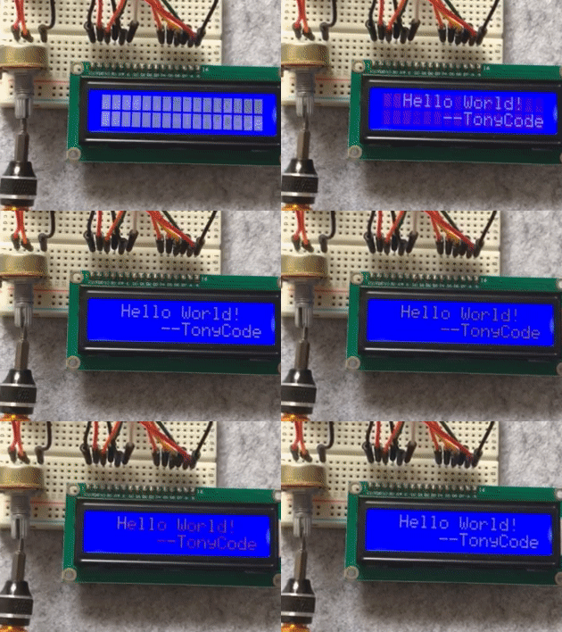
The LCD1602 displays the character “Hello World! –TonyCode”, and the display contrast can be adjusted using the potentiometer.
