For related content, click the card below to follow Arm Technology Academy
This article is authorized to be transferred from the WeChat public account TrustZone. This article mainly shares the communication between MailBox and MUTEX.
1 Preface
Many solutions in the industry now involve multiple processors, either hard-core processors like Arm A9, A53, or R5, soft cores like MicroBlaze, Arm Cortex-M1/M3, or a combination of both.
Arm Cortex-M1 is referred to as a soft-core processor mainly because it offers greater flexibility in design and application. Firstly, soft-core processors can be customized as needed. In design, Arm Cortex-M1 can be tailored to meet specific application requirements. For example, in hardware resource-limited situations, such as FPGA devices, Cortex-M1 can meet area budget requirements through optimized design. It adopts a three-stage 32-bit RISC processor architecture and uses efficient instruction sets, such as the Thumb-2 instruction set, enabling higher performance with limited hardware resources. Secondly, soft-core processors are also more flexible in application. They can be integrated into various hardware platforms, such as FPGA, ASIC, etc. At the same time, soft-core processors can be programmed and controlled using different programming languages, allowing them to adapt to more application scenarios and requirements. Due to their flexibility and adaptability, soft-core processors are increasingly popular in various application fields.
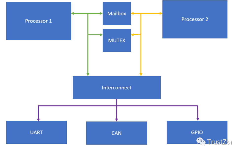
Figure 1
When implementing multi-processor solutions, we typically divide tasks among available cores, utilizing each core to maximize its performance attributes. For example, using MicroBlaze or Cortex cores in PL to execute dedicated real-time offloading tasks while using a hard-core application processor to handle higher-level functions.
If you have worked on complex SoC-related projects, you should be familiar with this, using a customized small core to assist the main processor in many tasks, or in multi-core SMP architectures, this kind of core-to-core communication mechanism is often seen.
Of course, to correctly implement multi-processor solution applications, all processors in the solution need to be able to communicate and share available system resources safely and reliably.
This is where inter-processor communication (IPC) comes into play; if implemented correctly, it can achieve secure and reliable communication between processors, while also allowing multiple processors to share common resources, such as UART, without causing damaging conflicts.
I previously wrote an article about core-to-core communication: 【Inter-core Communication Mechanism of SoC –> mailbox】. The industry also has communication solutions like IPC interrupts. Today we delve into the IPC implemented using mailbox and MUTEX.
MailBox and MUTEX play different roles in our IPC solution:
This uppercase and lowercase letter suddenly makes me uncomfortable but I don't want to change it haha● Mailbox – allows FIFO-based message passing methods for bidirectional communication between multiple processors.
● MUTEX – implements a mutex lock, allowing processors to lock shared resources to prevent multiple accesses simultaneously.
Whether we use heterogeneous SoCs or FPGAs, mailbox and MUTEX are implemented in programmable logic (PL).
Heterogeneous SoC (System on Chip) processors integrate multiple different architecture processing unit cores. For example, TI’s OMAP-L138 (DSP C674x + Arm9) and AM5708 (DSP C66x + Arm Cortex-A15) SoC processors, as well as Xilinx’s ZYNQ (Arm Cortex-A9 + Artix-7/Kintex-7 programmable logic architecture) SoC processors. Heterogeneous multi-core SoC processors combine the advantages of different types of processors. For example, Arm processors are cheap and energy-efficient, excelling in control operations and multimedia displays; DSPs are inherently designed for digital signal processing, excelling in specialized algorithm computations; FPGAs excel in high-speed, multi-channel data acquisition and signal transmission. At the same time, cores communicate through various means, quickly transmitting and sharing data, allowing heterogeneous multi-core SoC processors to achieve a 1+1>2 effect.
We can directly implement mailbox and MUTEX from the Xilinx IP library in the design. Since both are used for communication between two processors, they each have two AXI inputs.
Using mailbox or MUTEX provides each processor with an AXI interface.
In this example, we will use Zynq to communicate and share resources with MicroBlaze in PL.
MicroBlaze will connect to the GPIO that drives the LED.
To create a block diagram, we first need to add the Zynq processing system IP and run block automation to configure the selected board’s Zynq.
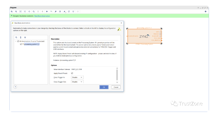
Figure 2
This is the added processing system. For the second one, use the IP directory to add MicroBlaze. Once the MicroBlaze IP appears in the block diagram, double-click to customize the IP, select the microcontroller preset, and keep all other options unchanged.
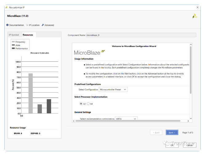
Figure 3
After configuring the MicroBlaze IP, the next step is to run its block automation to create the MicroBlaze solution. This will be added to the block RAM, from which MicroBlaze will run and debug facilities.
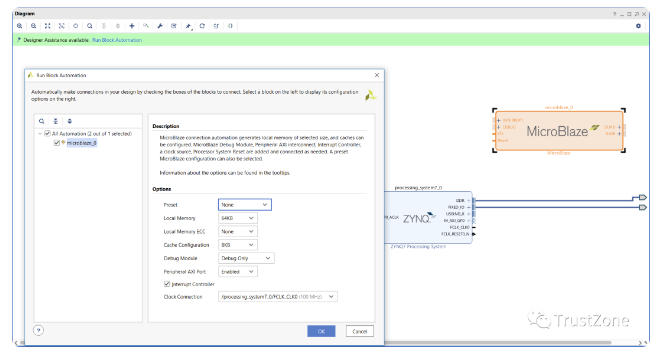
Figure 4
Now that we have our two processing system solutions, we are ready to add mailbox and MUTEX – both solutions can be added from the Xilinx IP directory.
Once completed, we can use the connection automation wizard to connect them to the AXI connections of the two processor systems.
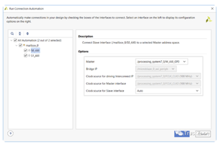
Figure 5
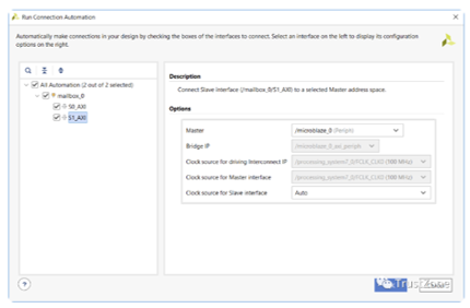
Figure 6
Mailbox uses FIFO to transfer messages, its depth can be configured by reusing the mailbox IP. To ensure effective processing of messages on the receiving processor, the mailbox can generate interrupts to the relevant processors while messages are queued.
Similar to mailbox, MUTEX is very similar, except it does not use FIFO, but uses registers for each MUTEX to indicate the lock state. We can share up to 32 MUTEX among up to 8 processors.
To prevent processors from inadvertently or maliciously unlocking the mutex, use the CPU ID.
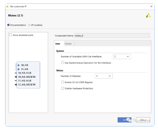
Figure 7
The completed block diagram should resemble the block diagram below.
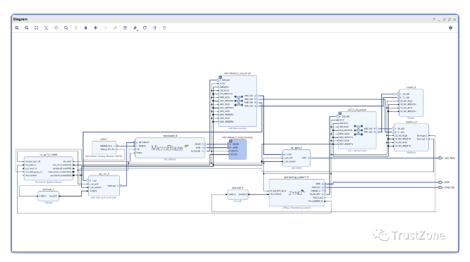
Figure 8
We can now build the hardware and export the design to the SDK, preparing to write the software application.
2 MailBox
We checked the hardware build required to implement inter-processor communication (IPC) mailbox and mutex in Vivado.
Now, we will explore how to use the mailbox to transfer data from one processor to another.
Remember, in this system, we are using one of the Zynq processing system (PS) A9 cores and MicroBlaze in programmable logic (PL).
Both processors connect to the mailbox using AXI, so we can easily implement sending and receiving messages using the APIs provided in the board support package (BSP).
Exporting the design from Vivado to Xilinx SDK will import the hardware specifications into the SDK. Checking the HDF file in the hardware project will show the memory mapping of MicroBlaze and Cortex-A9.
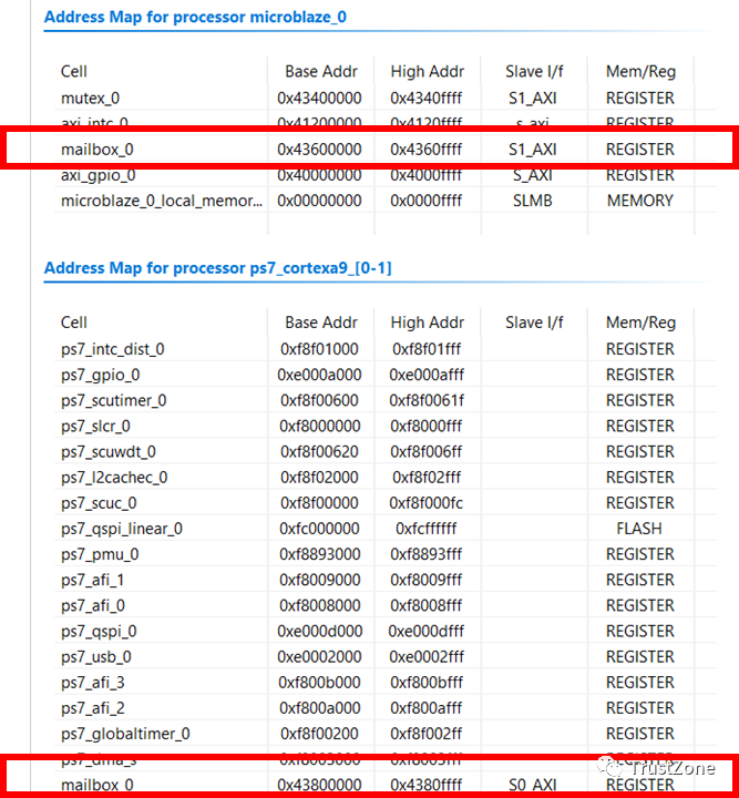
Figure 9
After importing the hardware definition, the next step is to create two applications – one for Arm Cortex-A9 and one for MicroBlaze. When creating these applications, ensure to select the appropriate processor and enable the application to also create the BSP.
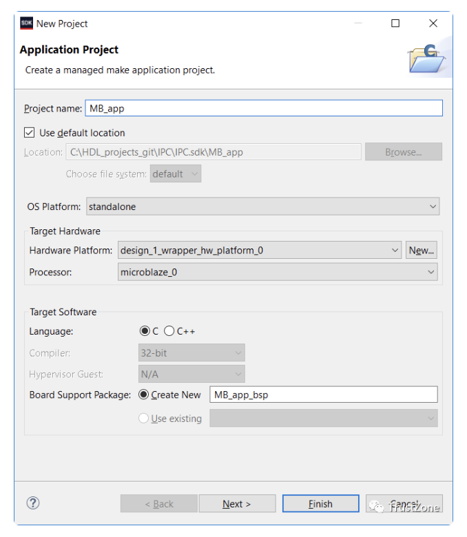
Figure 10
After completing this, we should have the following included in the SDK project explorer:
● A hardware platform that describes the Vivado design – this serves as the reference hardware platform for all applications and BSPs.
● Two board support packages – one for PS Arm A9 and one for MicroBlaze applications.
● Two applications – one for PS Arm A9 and one for MicroBlaze.
In this application, MicroBlaze will report when it starts running and the status of the LED being on or off.
To do this, we will use the mailbox API provided by the BSP, both providing the same API for use.
These files are included in the xmbox.h file, allowing us to initialize and configure the mailbox for use.
To read and write from the mailbox, there are several functions:
XMbox_Read ( XMbox * InstancePtr, u32 * BufferPtr, u32 RequestedBytes, u32 * BytesRecvdPtr)XMbox_ReadBlocking ( XMbox * InstancePtr, u32 * BufferPtr, u32 RequestedBytes )XMbox_Write(XMbox* InstancePtr,u32 * BufferPtr, u32 RequestedBytes, u32 * BytesSentPtr )XMbox_WriteBlocking ( XMbox * InstancePtr, u32 * BufferPtr, u32 RequestedBytes )In the above functions, the instance pointer references the mailbox declaration, and the buffer pointer points to where we store TX or RX data. While the requested bytes indicate the size of the transfer, the read and write functions also report the actual number of bytes sent or received, as this may differ from the requested byte count.
It is particularly noted that for all functions, the number of bytes sent or received should be a multiple of 4; if not, some padding will be required. If the requested bytes are not a multiple of 4, an assertion will be generated.
Of course, blocking reads and writes do not report the actual number of bytes sent or received, as the function will block until the requested byte count is sent or received.
In addition to sending and receiving functions, there are many internal management functions:
● Interrupt enable, status, and disable.
● Definition of send and receive interrupt FIFO thresholds.
● FIFO management and control, including checking empty and full, flushing, and resetting. By using these functions, we can create simple applications for Arm A9 and MicroBlaze.
The A9 program is straightforward. Once the mailbox is initialized, it will loop indefinitely waiting for messages from MicroBlaze, then print them through the terminal.
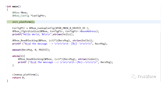
Figure 11
The MicroBlaze application is a bit more complex. It sends a message to the A9 core upon startup, and then each time it toggles the LED, it also sends a message about the LED status.
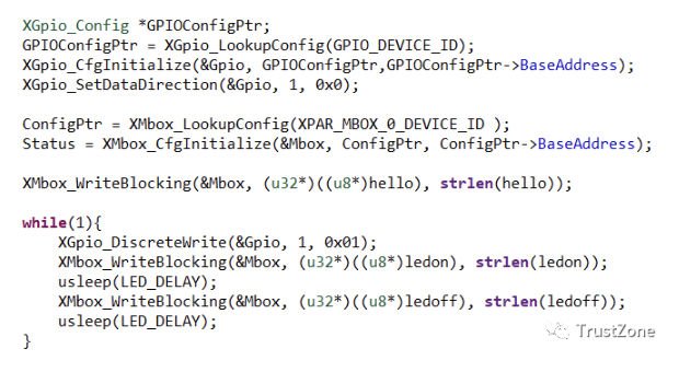
Figure 12
To run this on Zynq, we need to create a new debug configuration that downloads both processors. To ensure success in a multi-processor environment, we need to consider the startup of both processors. In this debug configuration, select:
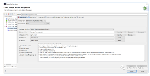
Figure 13
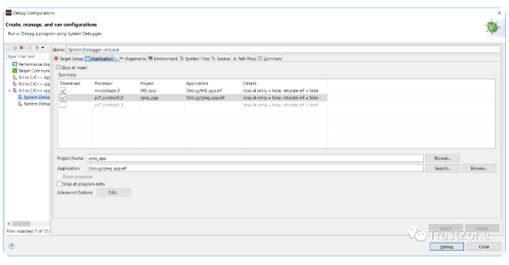
Figure 14
During the runtime of the debug configuration, the device will be configured, and the applications for both processors will be downloaded. Then, both processors will pause at the entry point of main().
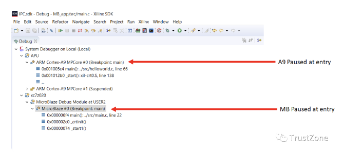
Figure 15
For this example application, please start the A9 processor first, then start the MicroBlaze processor.
When executing the above example code, you can see the following content in the terminal window:
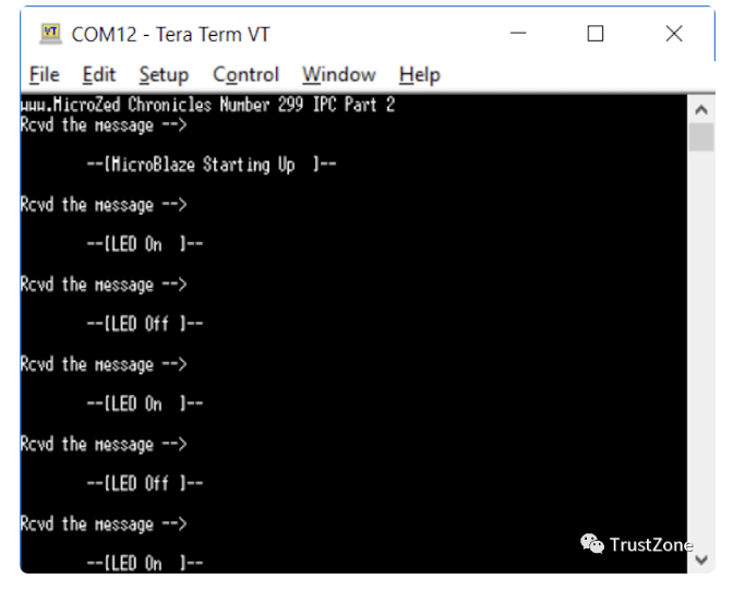
Figure 16
Both processors are communicating!
Next, we focus on the mutex.
3 MUTEX
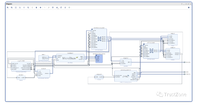
Figure 17
When our device has multiple processors, multiple processors may want to share common resources (such as memory or UART) simultaneously. If access to these resources is uncontrolled, it can quickly and easily lead to corruption. For example, serial port printing can become jumbled together.
Mutex seems to be one of the simplest problems, and of course, a flag can be used where both parties can test it; if it is free, it claims access to the resource.
However, a problem arises in the time between one processor testing and setting the flag, during which the other processor can also see the flag as free and start its locking process.
This is commonly referred to as a race condition, and other potential pitfalls surrounding mutual exclusion include deadlock and starvation. A processor cannot access resources (starvation) or the system locks up because each processor is waiting for different locking processes to occur (deadlock).
When mentioning mutex, deadlock issues are generally involved.
There are many solutions to address these issues, including using multiple flags. However, they begin to become very complex when considering anything beyond the simplest case, in short, they are not easy to scale.
The way to resolve race conditions is to ensure that the test and set operation is combined into one operation, that is, if we test the mutex flag and it is free, then it will be set.
This is exactly how Xilinx mutex works; when we write to the mutex, if it is free, the processor will be allocated resources.
Designing a mutex in our hardware design is very simple, each processor has its own AXI interface. Since the mutex can support 1 to 8 processors, we can simply use one interface when sharing resources between the operating system and tasks running on the same processor.
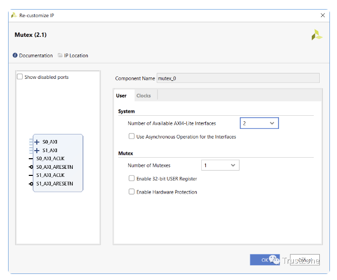
Figure 18
In an instance of mutex instantiation, we can implement up to 32 mutexes. However, for this example, we only have one. When implementing the mutex, we can also enable hardware protection at the AXI level if we wish.
If we choose to enable this feature, the optional AXI HWID field is used to lock and unlock the mutex, preventing the CPU from spoofing the CPU ID and incorrectly unlocking.
Each mutex also has an optional 32-bit register that can be used to share configuration data between processors if necessary.
When it comes to using mutexes in our software, we can use the Xmutex API (xmutex.h) provided for both processors in the board support package (BSP). In this API, we will find a class of functions:
● Lifecycle management – initialization and status reporting.
● User register – setting and clearing user registers.
● Mutex operations – functions for locking and unlocking mutexes.
Similar to the mailbox example we saw above, mutex operations provide blocking and non-blocking calls. Blocking calls are provided by the function XMutex_Lock(), while non-blocking function calls are XMutex_Trylock().
To demonstrate the application of mutexes, we will update our SW application so that the MicroBlaze application locks the mutex when setting the LED and unlocks the mutex when clearing the LED.
Then, the Zynq application will test the mutex and report whether it is set along with the LED status. A simple but effective example illustrating how mutex functions work.
The code for both processors is as follows.

Figure 19
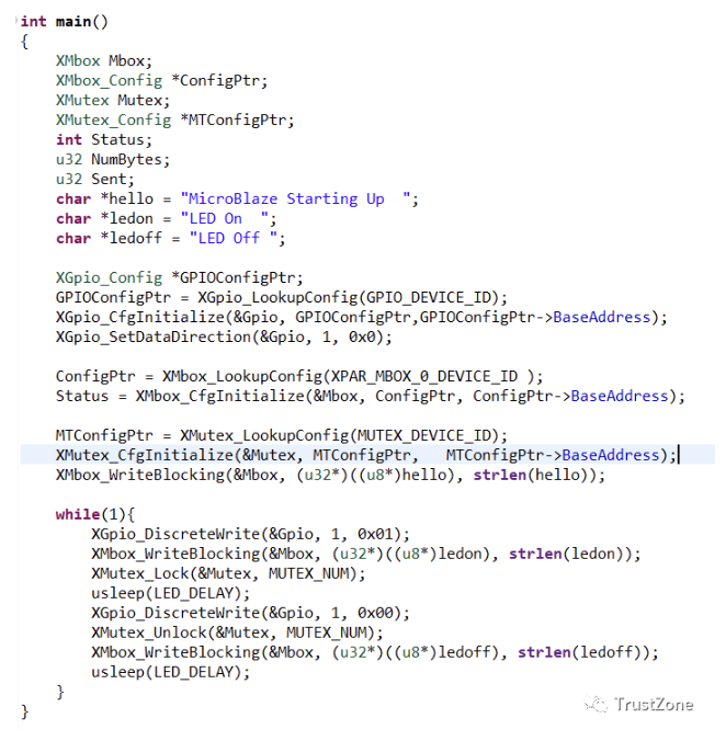
Figure 20
When running the application with the above code, the following can be observed in the terminal window. This indicates that MicroBlaze is locking and unlocking the mutex as expected when accessing the LED resource.
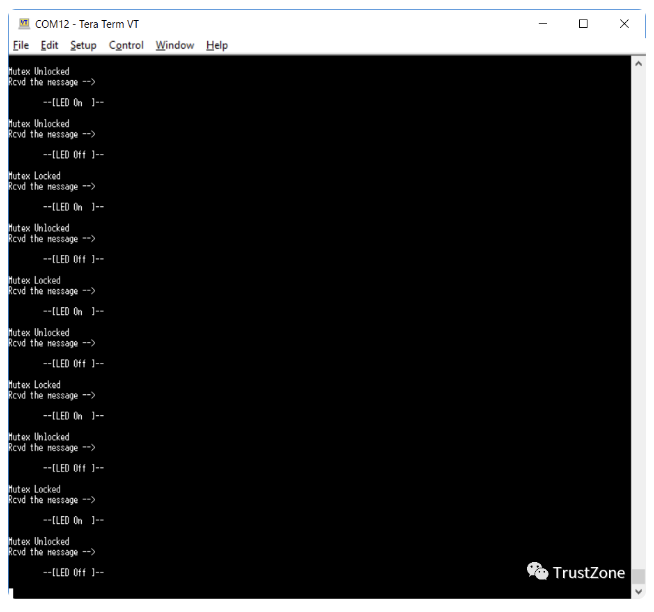
Figure 21
Recommended Reading
-
How does Modbus communication work?
-
Analysis of inter-core communication mechanism RingBuff
-
RTOS implementation of dual-core MCU message communication


Long press to identify the QR code to add Miss Ji’s WeChat (aijishu20), and join the Arm Technology Academy reader group.
Follow Arm Technology Academy
 Click the “Read Original” button below to read more articles about Platform Security Architecture (PSA) column.
