IoT Application Technologies in Smart Factories01
Abstract: Smart factories utilize IoT and monitoring technologies to enhance information management services. Through IoT platforms, the controllability of production processes can be improved, and manual intervention in production lines can be reduced. This article mainly introduces three levels of IoT platforms: the sensor network layer, the transmission network layer, and the application network layer, as well as three common wireless network technologies: ZigBee, Wi-Fi, and LoRa.
Keywords: Smart Factory; IoT; Zigbee Technology; Wi-Fi Technology; LoRa Technology
1 Introduction
Figure 1 shows the model of a smart factory, where an open IoT platform and advanced digital design platform serve as the foundation. By integrating product and asset management, production management, and utilizing big data analysis, cloud computing, and sensing technologies, the digital transformation of manufacturing can be achieved. In smart factories, the industrial IoT encompasses a wide-ranging, multi-level, and deep integration from production to service, from the device layer to the network layer, and from manufacturing resources to information fusion. Through the IoT platform in smart factories, the application of new generation information technologies such as cloud computing, big data, and digital virtualization can significantly enhance productivity and work efficiency, reduce costs, and minimize resource usage.
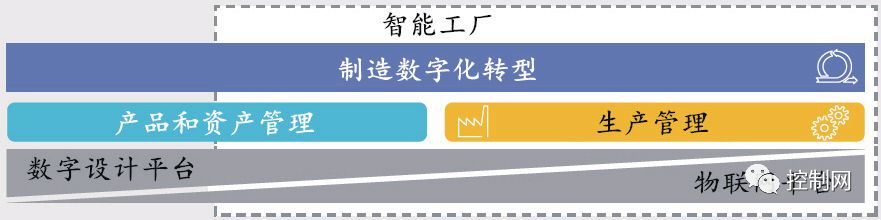 Figure 1 Smart Factory Model
2 IoT Platforms in Smart Factories
According to the direction of data flow and processing methods within the IoT network, the IoT platform for smart factories can be divided into three levels, as shown in Figure 2.
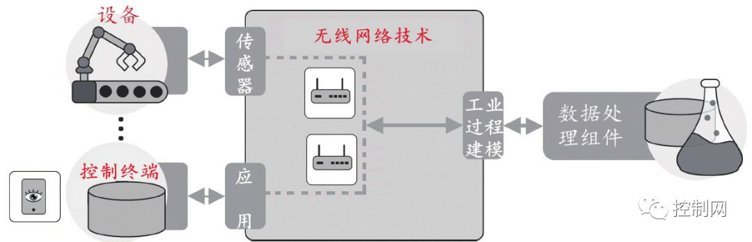 Figure 2 IoT Platform in Smart Factories
(1) Sensor Network Layer: This layer primarily uses QR codes, RFID, and sensors to identify manufacturing equipment, assembly lines, and other industrial devices, collecting data from perceived signals. Industrial sensors, as detection devices, can measure or sense the status of manufacturing equipment or products, such as position, temperature changes, concentration levels, and flow trends, converting relevant physical quantities in discrete or process manufacturing into electrical signals, communication codes, or other forms of information that can be transmitted, processed, and digitally stored. This is a prerequisite for achieving intelligent detection and control in manufacturing, monitoring the production process through the reading of various effective parameter signals.
(2) Transmission Network Layer: This layer utilizes wireless network technologies such as Zigbee, Wi-Fi, LoRa, broadcast networks, and mobile communication networks to facilitate data transmission and computation. In smart factories, the wireless network is a mesh network composed of numerous randomly distributed sensor nodes, which has self-organizing capabilities and transmits signals with ubiquitous collaboration and heterogeneous interconnection characteristics.
(3) Application Network Layer: This layer includes various input and output control terminals, such as computers, touch screens, tablets, and smartphones. The applications displayed on smart terminals are modeled industrial processes that have undergone data processing and are expressed in a tangible manner.
In the IoT platform of smart factories, two standardization issues also need to be addressed:
(1) Hardware Interface Standardization. Consistent hardware interface standards ensure that different IoT sensor device manufacturers can guarantee effective data transmission when connecting to the wireless network. For example, in the case of a certain sensor shown in Figure 3, an FPGA can generate driving pulses to the sensor itself and also transmit signals to the data acquisition circuit, with its wireless communication interface containing an MSP430 microcontroller and an nRF905 RF chip.

Figure 3 Example of Hardware Interface Standardization
(2) Data Protocol Standardization. Data protocols refer to the horizontal and vertical data flow exchange protocols of the three layers of the IoT platform, which can be divided into control data flow and management data flow.
3 Three Wireless Network Technologies of IoT
(1) ZigBee Technology
ZigBee technology is a cost-effective, energy-efficient, and stable short-range wireless networking communication technology. The wireless data transmission module of ZigBee networks can include up to 65,000 nodes and has self-organizing capabilities. Within the entire network coverage, each ZigBee node can serve as a signal collection and control monitoring object; within its own signal coverage, it can connect with multiple isolated sub-nodes that do not undertake network information relay tasks, automatically relaying data information from other network nodes.
As an open wireless LAN standard based on the IEEE802.15.4 protocol, ZigBee is particularly suitable for low-rate data transmission between lower-level devices in factories. It operates in three frequency bands, including the commonly used ISM band in China at 2.4GHz, which is characterized by no application required and is free to use with 16 channels; the 868MHz band in Europe, which has 1 channel; and the 915MHz band in the USA, which has 10 channels.
According to the OSI model, ZigBee networks are divided into four layers: Physical Layer (PHI), Media Access Layer (MAC), Network Layer or Security Layer (NWK), and Application Layer (APL), as shown in Figure 4. In the network layering, the physical layer provides data and management services to the media access layer, proceeding from bottom to top. In the adoption of protocol standards, the lowest PHI and MAC layers use the IEEE802.15.4 protocol standard, while the NWK and APL layers are standardized by the ZigBee Alliance.
| Application Layer (APL) | ZigBee Alliance |
| Network Layer/Security Layer (NWK) | |
| Media Access Layer (MAC) | IEEE 802.15.4 |
| Physical Layer (PHI) |
Figure 4 ZigBee Network Layering
Star, tree-cluster, and peer-to-peer topologies are the three types supported by ZigBee, as shown in Figure 5. In the figure, routing nodes complete the relevant data routing, and terminal node information generally needs to be forwarded through routing nodes before reaching the coordinator node, which is responsible for network management. The star network is the simplest type, where nodes do not communicate directly with each other, and all data information must be relayed through the coordinator node. In a peer-to-peer network, nodes are interconnected, and data forwarding generally occurs in a multi-hop manner, with each node having forwarding capabilities. The tree-cluster network is the most complex structure, consisting of coordinator nodes, routing nodes, and terminal nodes. Typically, large-scale equipment monitoring in factories is completed through peer-to-peer networks, while star and tree-cluster networks are one-to-many.
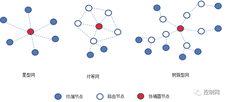 Figure 5 Zigbee Topology Structure
(2) Wi-Fi Technology
Wi-Fi stands for Wireless Fidelity, which adopts an 11Mbps wireless standard—802.11b. The greatest advantage of Wi-Fi is its high transmission speed and long effective distance, achieving a transmission speed of 11Mbps and a transmission distance of about 300m for commercial devices. Figure 6 shows the protocol stack of Wi-Fi networks, and Figure 7 illustrates the structure of Wi-Fi networks.
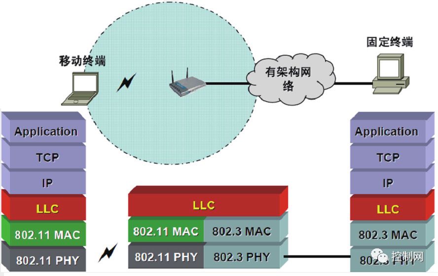 Figure 6 Protocol Stack
 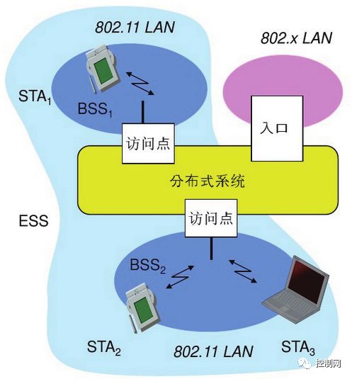 Figure 7 Wi-Fi Network Structure
In Wi-Fi networks, the station (STA) refers to various terminal devices with Wi-Fi communication capabilities, such as smartphones, tablets, and touch screens, that are connected to the wireless network. BSS (Basic Service Set) can consist of an access point and several stations, or just several stations (at least two). A BSS with an access point is called a infrastructure BSS; a BSS without an access point is called an independent BSS, or AdHoc Network. ESS (Extended Service Set) is a distributed system formed by connecting one or more BSSs together. Through the extended service set, the coverage of the Wi-Fi wireless network can be expanded to cover the entire set of devices in the manufacturing factory.
(3) LoRa Technology
LoRa is a LPWAN communication technology first launched by Semtech in the USA and widely implemented worldwide. It employs spread spectrum communication, offering advantages such as long-distance transmission, low power consumption, and multi-node networking. Currently, LoRa operates mainly in the 915MHz, 868MHz, and 433MHz frequency bands, all of which belong to free frequency bands.
Figure 8 illustrates the LoRa network, which mainly consists of LoRa terminals (which can have built-in LoRa modules), LoRa gateways (or base stations), and servers including network servers and application servers, forming a typical star topology. In this structure, the LoRa gateway acts as a transparent relay to connect the on-site LoRa terminal devices with remote servers, facilitating bidirectional transmission of various data from devices, processes, and remote servers, such as sensor data, standard processing data for modeling, and processed data sent to the application layer.
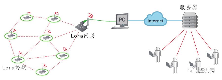 Figure 8 LoRa Network
4 Conclusion
In the construction of smart factories, analyzing the data collected through IoT can help industrial enterprises assess the status of various devices or products, achieve early warning or alarms for abnormal conditions, and thus enable predictive maintenance to avoid unplanned downtime. It also aids enterprises in improving product performance, reducing energy consumption, ensuring safety, and promoting improvements in capacity, emissions reduction, and efficiency in manufacturing enterprises.
Complex System Simulation Technology in Smart Factories02
Abstract: The simulation of complex systems is a technology that reflects the system behavior or process of smart factories through simulation experiments using simulation hardware and software, aided by numerical computation and problem-solving. This article mainly introduces two categories of simulation technologies in smart factories: simulation technology for discrete manufacturing and simulation technology for process manufacturing.
Keywords: Smart Factory; Simulation Technology; Complex Systems
1 Introduction
Figure 1 shows the model of a smart factory, where the simulation of complex systems is an important part of product and asset management and production management. It reflects the system behavior or process of smart factories through simulation experiments using simulation hardware and software, aided by numerical computation and problem-solving.
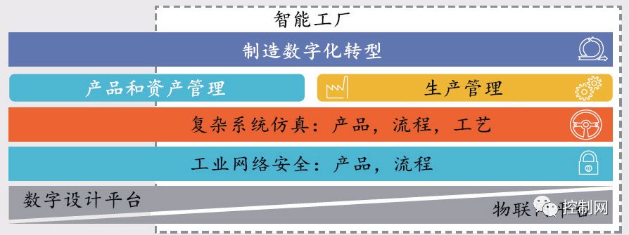
Figure 1 Smart Factory Model
With the rapid development of information processing and network technologies, the data information transmitted from actual factories and the computer-integrated simulation system form a virtual factory simulation environment. The IoT platform connects factory operators and product development personnel to collaboratively research and plan objectives, promptly identifying and resolving product, process, and technology issues, as shown in Figure 2.
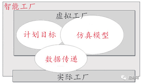
Figure 2 Simulation Environment of Smart Factory
The simulation technology of smart factories can be roughly divided into two categories based on the differences in simulation models and experimental methods: simulation technology for discrete manufacturing and simulation technology for process manufacturing.
2 Simulation Technology for Discrete Manufacturing in Smart Factories
In smart factories, discrete event system simulation methods are mainly applied in discrete manufacturing industries, such as injection molding, stamping, and sheet metal, integrating the following processes: product development, testing and optimization, production process development and optimization, and factory design and improvement.
Through virtual machine tool processing systems, processing technology can be optimized, processing quality can be forecasted and detected, and cutting parameters and tool paths can be optimized to improve machine tool utilization and production efficiency. Common CNC machine tools mainly consist of components such as the bed, column, motion axes, and worktable, along with tools, fixtures, and some auxiliary components.Virtual machine tools are mainly categorized into three types based on structural characteristics: general modules, auxiliary modules, and specialized modules. General modules refer to common components shared by various machine tools, while auxiliary modules refer to tools such as cutters and fixtures. Specialized modules are established for special machine tool components.
The modeling process for virtual machine tools using Vericut simulation software is as follows:
(1) Preliminary Preparation. Clarify the model of the CNC system, machine structure, dimensions, working principles, spindle travel, coordinate systems, and raw materials, tools, and fixtures.
(2) Machine Tool Construction. The software provides several common machine tool models for use, but they generally do not meet specific needs. In this case, users need to construct their own machine tools.
(3) Machine Tool Control System Settings. Users can select the control system from VERICUT based on the actual machine tool used. If the control system does not exist, it can also be customized according to IEC61131-3 rules.
(4) Establishing the Machine Tool Tool Library.
(5) Setting Machine Tool System Parameters.
For a product processing, as shown in Figure 3, the sample three-axis milling machine provided by Vericut software meets the requirements, and the simulation results are shown in Figure 4.
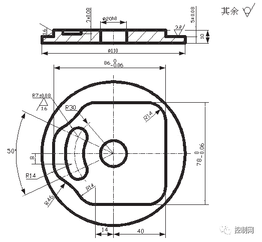
Figure 3 Processed Parts
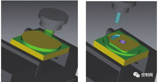
(a) Simulation Result One (b) Simulation Result Two
Figure 4 Three-Axis Milling Virtual Machine
The design and simulation of mechanical products can make the planning of manufacturing workshops more efficient, allowing project-related personnel to quickly understand the plan, thus avoiding potential errors and reducing many failure costs, enabling the smooth mass production of the entire manufacturing workshop’s automation system and personnel operation engineering.
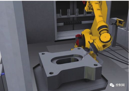
Figure 5 Intelligent Model
In addition to mechanical processing, discrete manufacturing simulation software must also possess numerous intelligent models, as shown in Figure 5, including a vast database of 3D models for industrial robots, mechanisms, and logistics systems, enabling rapid factory planning and design. After integrating practical application experience, it can accurately predict manufacturing activities, ensuring the benefits of introducing manufacturing factories.
Figure 6 shows the application of Visual Components virtual simulation software on production lines, which features rapid functionality for immediate use, significantly enhancing the efficiency of robot simulation and logistics simulation, while integrating PLC and robot simulation functions for offline programming of robots or PLCs.
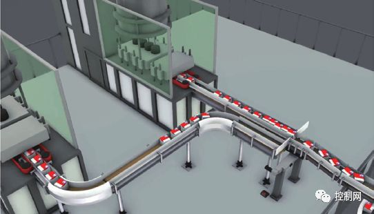
Figure 6 Application of Visual Components Software
3 Simulation Technology for Process Manufacturing in Smart Factories
Process manufacturing refers to industries such as paper making, steel, chemical, and textile, where the processed objects continuously pass through production equipment, undergoing a series of processing devices such as flow boxes, blast furnaces, reaction kettles, and winding machines to achieve chemical or physical changes, ultimately producing products like paper, steel, polyethylene, and long fibers.Due to the strong variability of materials and numerous constraints in process manufacturing, there are significant differences in production processes compared to discrete manufacturing industries.
Figure 7 illustrates the actual production process and simulation process in process manufacturing. Process manufacturing often operates through DCS, PLC, and other control systems, facilitating bidirectional data transmission of operational and production information. The simulation system based on virtual DCS mainly consists of process simulation and control simulation. Figure 8 shows that process simulation refers to simulating the actual devices on-site through dynamic process mathematical models, implemented by process simulation software composed of process simulation servers and process mathematical models; control simulation refers to simulating DCS control systems, including the simulation of configuration control logic and virtual DPU technology.
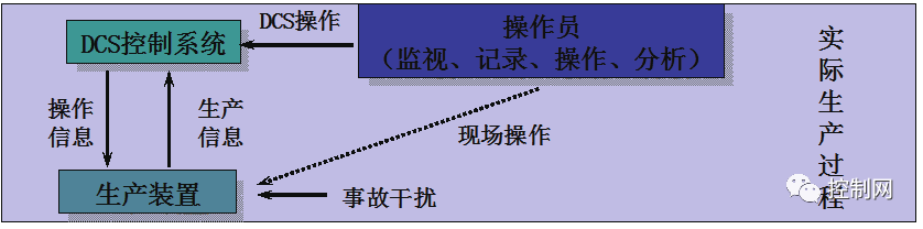
(a) Actual Production Process
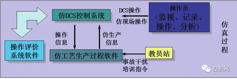 (b) Simulation Process
Figure 7 Actual Production Process and Simulation Process
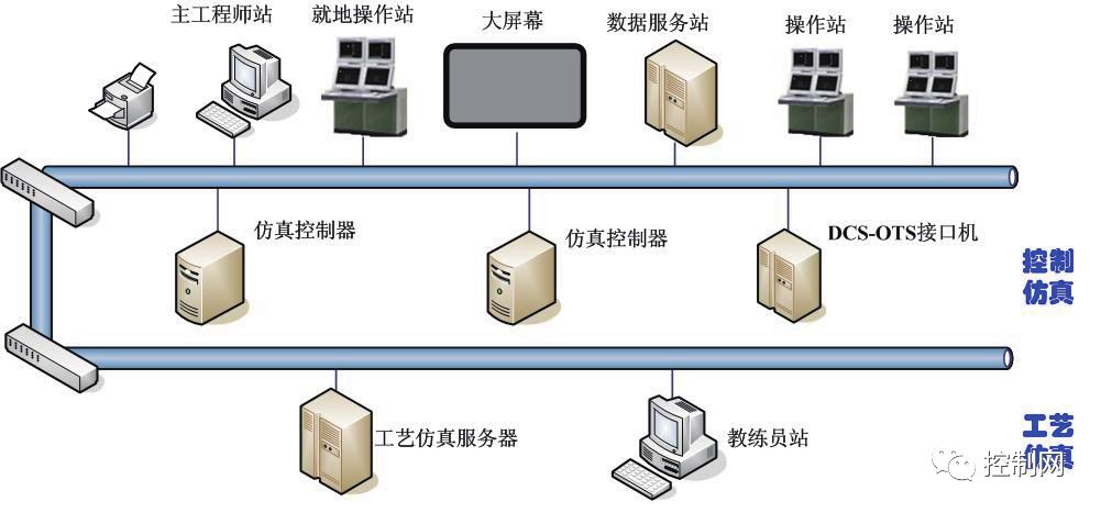
Figure 8 Control Simulation and Process Simulation
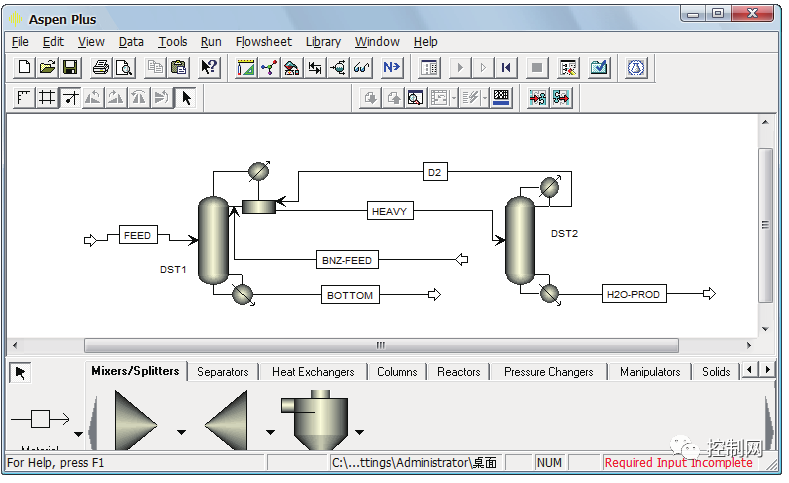
Software running on process simulation can be selected based on actual production processes, such as the large-scale general process simulation system AspenPlus, which simulates the constant boiling distillation process of anhydrous ethanol as shown in Figure 9. In Figure 9(a), industrial ethanol and benzene enter the constant boiling distillation tower, and the resulting ethanol-water-benzene ternary constant boiling mixture is vaporized from the top of the tower. Since this constant boiling mixture contains a significant amount of water, the bottom of the tower extracts nearly pure ethanol. The vapor from the top of the tower enters the condenser, where part is refluxed, and another part enters the separator. The light phase in the separator returns to the constant boiling tower to supplement the reflux, while the heavy phase enters the benzene recovery tower. The vapor from the recovery tower enters the condenser, and the bottom product of the tower is dilute ethanol. Sometimes, the bottom product of the recovery tower is sent to another ethanol recovery tower, where the bottom product ultimately yields nearly pure water. Since benzene is recycled in the process, only a small amount of benzene needs to be periodically supplemented to maintain the operation of the constant boiling tower. In Figure 9(b), a “RadFrac” module with a decanter simulates the constant boiling tower: the input information for the constant boiling tower feed includes pressure, vaporization rate (or temperature), and component flow rates (or flow and composition); in the “Components” section of “Specifications,” ethanol, water, and benzene are searched by their English names or molecular formulas and added to the component list; in Properties→Global→Basemethod, the thermodynamic calculation method NRTL is specified; in Blocks→DISTl, the parameters for the constant boiling tower equipment are entered, setting the number of trays, condenser type, effective phase as gas-liquid-liquid, and convergence algorithm as constant boiling algorithm.
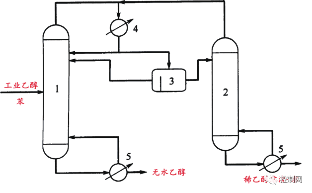
(a) Anhydrous Ethanol Constant Boiling Distillation Process
1: Constant Boiling Distillation Tower;2: Recovery Tower;3: Separator;
4: Condenser;5: Reboiler
(b) Anhydrous Ethanol Constant Boiling Distillation Simulation Process Diagram
Figure 9 Actual and Simulated Process Diagram of Anhydrous Ethanol Constant Boiling Distillation
Table 1 shows the logistics output information calculated by AspenPlus based on the input information.
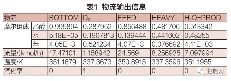
In the simulation system of process manufacturing, process model modeling is completed in the simulation software based on process diagrams and graphical modeling forms. Simulation software generally has a mature process model library, enabling rapid modeling while completing dynamic and static debugging. For the information collection part, reasonable planning is required during the preliminary modeling phase, reserving interfaces with various systems to achieve associations with other operating parameters.
4 Conclusion
By using virtual simulation software tools, it is possible to simulate more discrete manufacturing or process manufacturing production sites in a short time. At the design stage, the effectiveness of production equipment can be planned and verified, and during operation, it can be used for training or process monitoring. Additionally, by incorporating mathematical modeling methods into simulation software, virtual systems can be made closer to real systems, contributing to the prediction of production processes.
Production Management Technology in Smart Factories03
Abstract: Production management is a comprehensive management activity that plans, organizes, and controls production activities. By implementing workflow technology in smart factories, various resources of enterprises, such as people, information, application tools, and business processes, can be effectively organized together, improving the reusability of manufacturing execution system software.
Keywords: Smart Factory; Production Management Technology; Manufacturing Execution System; Industrial Control System
1 Introduction
Figure 1 shows the model of a smart factory, where production management is a comprehensive management activity that plans, organizes, and controls production activities. By reasonably organizing the production process, effectively utilizing production resources, and conducting production activities economically and reasonably, the expected production goals can be achieved.
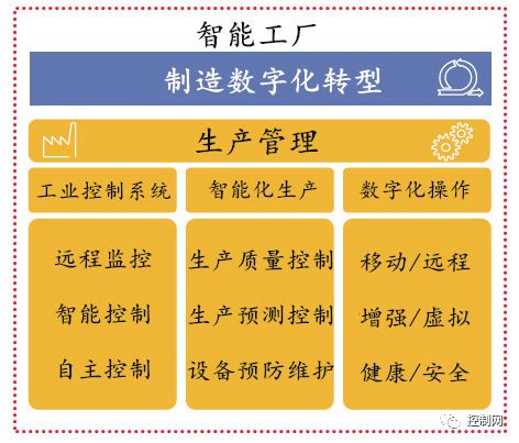 Figure 1 Smart Factory Model
The production management technology of smart factories is mainly divided into two levels (as shown in Figure 2): Manufacturing Execution System (MES) and Industrial Control System, where MES connects the enterprise’s production planning with the industrial control system of workshop operations, while the industrial control system includes sensors and actuators (including data collectors, barcodes, various measuring and testing instruments, robotic arms, etc.), control systems (PLC/DCS), and remote control (SCADA). Additionally, digital operations are the most important manifestation of human-machine coordination in smart factories, including the latest technologies such as mobile/remote operations, augmented/virtual operations, and health/safety operations.
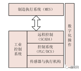 Figure 2 Production Management Levels
2 Manufacturing Execution System of Smart Factories
In traditional manufacturing processes, workers must report to supervisors after completing each operation, and supervisors then assign the next operation, resulting in certain waiting times that significantly reduce production efficiency. In smart factories, the introduction of the Manufacturing Execution System (MES) allows for intelligent navigation of the manufacturing process based on the abstract and generalized description of the required or generated relevant data according to workflow and business rules between various operational steps, providing on-site operators with intuitive information on batch tasks to be executed or processed. The task item manager then manages the executed tasks, and feedback from on-site operators allows for the addition of new task items to the workflow task list and the deletion of completed tasks, a process referred to as “workflow technology.”
The workflow technology of the Manufacturing Execution System is a technical means that effectively controls and coordinates the execution of complex activities, enabling interaction between on-site operators and management application software such as ERP. By adopting workflow technology, the business logic of MES can be separated from specific business implementations. This method has significant advantages in practical enterprise applications, allowing for changes in system functionality or performance improvements by modifying or redefining process models without altering hardware environments, operating systems, database systems, programming languages, application development tools, or user interface implementation methods.
As shown in Figure 3, the MES development process based on workflow separates the business process logic of MES from specific business implementations, extracting atomic-level enterprise business activities and using components to implement these atomic activities, driven by business process models to run these activities, achieving comprehensive integration of enterprise business and software implementation.
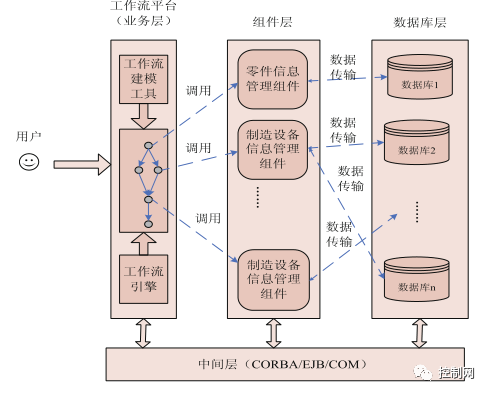 Figure 3 MES Development Process Based on Workflow
In the MES system, workflow technology can be used to design and establish a workflow environment to support business process analysis, business component extraction, business system construction, and business system execution for factory production management, as shown in Figure 4.
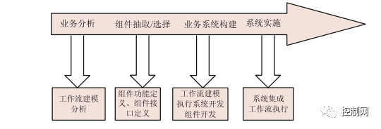 Figure 4 MES Establishment Process Based on Workflow
The basic unit of the MES workflow is the operation, where each operation’s data includes start conditions, end conditions, status, and processing data. The information transfer between operations is controlled by control connection arcs and data connection arcs. Figure 5 shows the internal structure diagram of the MES operation.
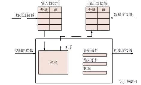 Figure 5 Internal Structure Diagram of MES Operation
In actual workshop processing, when on-site operators log into the MES, the workflow engine first reads the corresponding task list for that device from the task list and displays it on the device’s screen, including the processing data required for the operation to guide workers. Once an operation is completed, the task list is updated with relevant information from the operators based on process definitions and workflow-related data, and the workflow engine retrieves the next operation and its corresponding equipment to assign to relevant workers, refreshing the operator’s client task list in real-time to notify them to proceed with processing and providing necessary process documentation and data.
3 Industrial Control System of Smart Factories
Smart factories are based on the core of traditional industrial control systems, especially upgraded from PLC/DCS foundations. PLC/DCS has powerful industrial control programming capabilities, and with the emergence of fieldbus technology, independent PLC/DCS systems are no longer information islands. With technological advancements, real-time Ethernet technology has gradually become an option for industrial control systems, and even in real-time Ethernet products, support for fieldbuses such as CANOpen is now available. Additionally, as the computational capabilities of industrial control systems continue to improve, the capacity and demand for data exchange are also increasing.
With the emergence of IoT platforms in smart factories, the boundary between the control layer where industrial control systems (especially PLCs) reside and the management layer of MES systems is no longer so distinct. In this data-driven era, industrial information or product data is the greatest asset of enterprises, and technological innovation cannot solely rely on customer satisfaction; it must also be informed by data feedback, such as whether program operations are smooth and the impact of application scenarios on equipment.
Figure 6 shows the topology diagram of industrial control systems, where PLCs and other control systems not only operate automatically according to device application programs but also aggregate data with IoT platforms through PLC gateways and exchange data with MES systems, transmitting basic parameters such as equipment operating time and product quantity in real-time to the MES system, establishing star topology connections with management application software such as ERP, as shown in Figure 7.
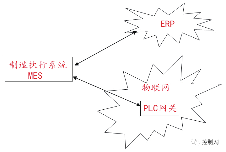 Figure 6 Topology Diagram of Industrial Control Systems
 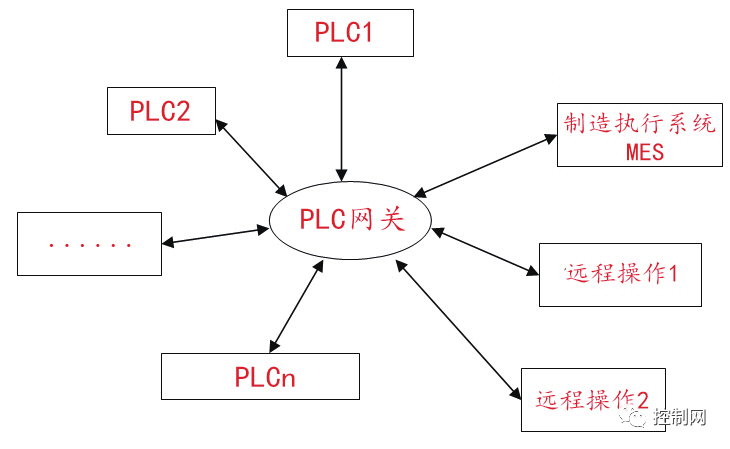 Figure 7 PLC Gateway Topology Diagram
Figure 8 is a topology diagram of intelligent piece management and production line equipment monitoring solutions for factory production workshops, enabling intelligent management of multiple production workshops. When production data is aggregated into the Manufacturing Execution System (MES), it can be viewed in real-time on local servers, and corresponding mobile apps or web servers can be developed, allowing personnel to manage remotely even when away from the site.
The system’s working process is as follows: The LoRa module, as the core device of the IoT platform, collects counting data from PLCs, CNC lathe PLCs, and other PLCs, establishing a wireless connection with the LoRa IoT network through F8L10T. The LoRa IoT network then aggregates production-related data to the Manufacturing Execution System (MES) via the F8926-L gateway through 3G/4G networks using TCP/IP protocols. A web platform is deployed on the server, allowing managers to log in via a browser to view production data, monitor output and capacity in real-time, and manage scientifically; mobile apps can also be developed to connect to the server, allowing production data to be downloaded from the server for convenient and quick office work anytime, anywhere.
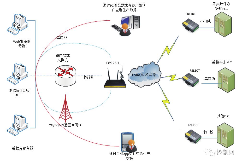 Figure 8 Solution Topology Diagram
4 Conclusion
By implementing workflow technology in smart factories, various resources of enterprises, such as people, information, application tools, and business processes, can be effectively organized together, improving the reusability of manufacturing execution system software. The workflow-based MES system can also flexibly collect various on-site data from industrial control systems through the IoT platform and process the data, maximizing the efficiency of smart factories.
Source: “Smart Manufacturing Home” WeChat Official Account, Ningbo International Machine Tool Equipment Exhibition WeChat Official Account is for sharing only; please contact for deletion if infringing.