There are many types of displacement sensors, and their application fields have been continuously expanding in recent years. More and more innovative technologies are being applied to sensors. We will explore various types of displacement sensors through several typical applications in industrial production.
Application of Displacement Sensors in Shield Tunneling Machines
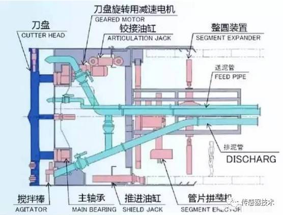
In tunnel construction equipment, different types of shield tunneling machines have different structural characteristics and supporting facilities. On some complex shield machines, the functions of the shield machine are systematic and diverse, including various functions such as mechanical, hydraulic, measurement, and control. For example, some composite shield machines include excavation systems, main drive systems, propulsion systems, grouting systems, hydraulic systems, and more.
As a type of linear sensor, displacement sensors are mainly used to measure mechanical displacement on linear positions. Each group of hydraulic cylinders in the shield machine’s propulsion system is equipped with displacement sensors to measure the displacement data when the hydraulic cylinders are pushed. The grouping of hydraulic cylinders in the shield machine propulsion system is usually divided as shown in the figure below: top (Group A), right (Group B), bottom (Group C), and left (Group D). Each group of hydraulic cylinders is individually installed with displacement sensors.
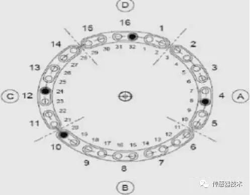
During propulsion, the hydraulic cylinder extends, applying force to the segment to provide the reaction force for the advancement of the shield machine. The pressure of the hydraulic cylinders can be adjusted independently. By monitoring the propulsion data of each group of hydraulic cylinders through the displacement sensors, construction personnel in the control room can monitor the stroke and pressure of each group of hydraulic cylinders in real-time. By adjusting the propulsion pressure and speed of each group of hydraulic cylinders, the shield machine’s correction and direction can be achieved.
Application of Static Magnetic Grating Displacement Sensors in Elevator Control Systems
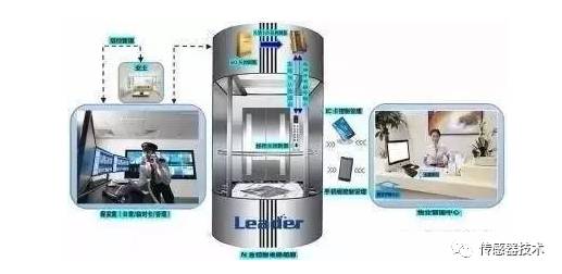
Elevators are important transportation tools related to the safety of people’s lives and property in modern buildings. They consist of a complete set of equipment for fixed lifting between floors, including the hoisting traction system, guiding system, safety devices, and electrical control system. Improving the operating efficiency of elevators, reducing energy consumption, minimizing mechanical wear, and extending the service life of elevators are all very important research topics.
Currently, there are two common control methods for elevators. One method uses a microcomputer as the signal control unit to achieve automatic scheduling and collective operation functions, while the drag control is completed by the inverter. The second control method replaces the microcomputer with a programmable logic controller (PLC) to achieve signal selection control.
The role of static magnetic grating displacement sensors in elevator control systems is to adjust the leveling control. The electrical control system acts as the “central nervous system” of the elevator. To ensure high operating efficiency, acceleration and deceleration should have appropriate limits and changes should be smooth, requiring a reasonably designed electrical control system.
Static magnetic grating displacement sensors consist of two parts: the “static magnetic grating source” and the “static magnetic grating ruler.” The “static magnetic grating source” consists of a passive neodymium-iron-boron magnetic grating array sealed with aluminum alloy; the “static magnetic grating ruler” is a specially designed high-strength aluminum alloy tube embedded with a microprocessor system, using switch-type Hall sensor elements to form a Hall coding array, with the outer aluminum alloy tube treated for anti-oxidation.
The “static magnetic grating source” moves in a non-contact manner (with a relative gap tolerance and posture tolerance of up to 50mm) along the axis of the “static magnetic grating ruler” to generate digital displacement information, producing digital signals with displacement values exceeding the millimeter level. By fully utilizing the resources of the embedded microprocessor, the data update speed is increased to the millisecond level to adapt to displacement responses at speeds below 5m/s.
The control part of the elevator leveling automatic control system is the static magnetic grating displacement sensor, as shown in the installation diagram below.
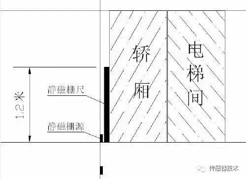
The static magnetic grating source is installed parallel to the elevator shaft and outdoor layers, with one for each floor, while the static magnetic grating ruler is installed on the car, measuring 1.2 meters long. Two static magnetic grating sources are installed in the basement to detect whether the car is at the bottom position and its direction of movement.
Since the operation of the elevator is controlled based on the call signals from the floors and the car, and the calls are random, the system control uses random logic control. That is, based on the basic control requirements achieved through sequential logic control, the elevator’s operation is controlled in a timely manner according to random input signals and the corresponding state of the elevator. Moreover, the position of the car is determined by the static magnetic grating displacement sensor and sent to the PLC counter for control. At the same time, a static magnetic grating source is set for each floor to detect the system’s floor signals.
The static magnetic grating displacement sensor is used to achieve elevator leveling control, enabling intelligent elevator control, ensuring good comfort during operation, and maintaining comfort levels during start, deceleration, and leveling regardless of changes in the car’s load.
LVDT Linear Displacement Sensors Ensure Efficient Operation of Gas Turbines
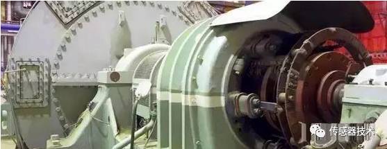
Gas turbines contain various control valves, such as those for regulating or blocking airflow. The precise monitoring and control of airflow from these control valves enable gas turbines to operate efficiently while minimizing energy waste. Actuators move the control valves, while feedback devices relay the valve position information back to the gas turbine control system, indicating the valve’s open and close status and degree.
Although other technologies have been considered as feedback devices, the power generation industry has standardized on LVDT linear displacement technology. LVDT displacement sensors are simple devices that consist of only a few coils and a ferromagnetic core, capable of withstanding high-intensity shocks and vibrations, and meeting specifications even when operating in extremely dirty conditions. Lasers cannot function in the presence of dust and dirt, while capacitive and eddy current sensors cannot measure long strokes. Potentiometers, magnetic resistance displacement sensors, and cable-operated displacement sensors do not meet temperature, vibration, and intrinsic safety requirements effectively.
LVDT displacement sensors are simple devices that consist of only a few coils and a ferromagnetic core, capable of withstanding high-intensity shocks and vibrations, and meeting specifications even when operating in extremely dirty conditions.
LVDT linear displacement sensors can measure movements of various sizes, down to one millionth of an inch, which is crucial for measuring the movement of certain valves to a minute level. For example, since the exhaust valve is a regulating valve, it must be opened to a specific degree depending on the power generation output. By confirming that the valve has opened to the appropriate degree, the plant can improve operational efficiency and achieve fuel savings.
LVDT linear displacement sensors can now be packaged using modern materials such as alloys and titanium to cope with the extreme temperatures and highly unstable environments commonly found in gas turbines. Special alloys such as cobalt and nickel can enhance the performance of LVDT sensors.
Due to the presence of gas vapor in gas turbines, LVDTs installed in gas turbines must comply with intrinsic safety parameters and must be certified by organizations such as Underwriters Laboratories (UL), FM, CSA, and ATEX. Even when designed for use in hazardous conditions, certifications provide end-users with peace of mind, assuring them that the sensors are approved for use in many hazardous environments of gas turbines.
In environments where sensors are used to monitor the normal operating conditions of gas turbines or to adjust valves, temperatures can reach +250°C. These sensors can separate the LVDT electronic devices located on the gas turbine control system from the LVDT coils.
Traditionally, the stroke of LVDT linear displacement sensors was too long for applications with limited space. Thanks to new computerized winding technologies and smaller embedded microprocessors, the body length of linear displacement sensors has been significantly reduced compared to their measurable stroke lengths. Today’s modern LVDTs have been reduced in size by up to 80%, making them suitable for any given stroke, allowing for high accuracy and durability.
LVDT linear displacement sensors are reliable, reusable, accurate, and cost-effective, playing a vital role in both the operation of gas turbines and factory retrofit projects, maximizing efficiency.
High Precision Control of Displacement Sensors in Quantitative Filling Machines
Rotary automatic quantitative filling machines are advanced production equipment that beverage and liquor manufacturers are purchasing in large quantities. They adopt a filling method that combines quantitative filling: each electrically controlled filling valve is equipped with a measuring cylinder, controlled by a liquid level sensor (float type) for quantitative replenishment and filling. The liquid is first transferred from the material tank to the measuring cylinder, and then filled into the packaging container.
This is a dynamic metering quantitative form, and achieving precise measurement and control while the equipment operates at high speed is a significant challenge.
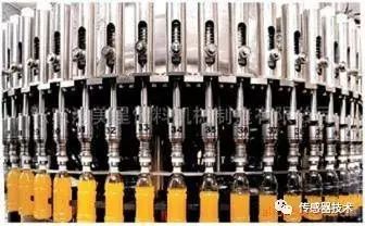
The key technical difficulty in dynamic metering is the precise detection of the liquid level in the measuring cylinder. Magnetostrictive displacement sensors perfectly meet the technical requirements for precise quantitative filling with their reliability, high resolution, minimal temperature drift, and rich interface signals, becoming standard components in mainstream rotary automatic quantitative filling machines.
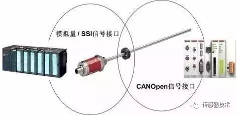
Magnetostrictive sensors transmit the high-precision detected displacement values to the automation control system through matching signal interfaces. Mature solutions typically use one of three types of signals: analog signal, SSI serial synchronous signal, or CANOpen bus signal to construct the system.
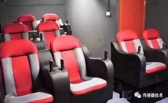
Application of Displacement Sensors in Entertainment Motion Devices
In the entertainment motion stage of simulated actions, the demand for displacement sensors is also very high. Currently, in many large entertainment venues in various cities, from small motorized flying ships that can only accommodate 2 to 3 people to large dynamic cinemas that can accommodate dozens or even hundreds of people, these systems are widely seen. Especially in large theme parks like Disney World and major movie studios. To meet the safety and stability requirements of mechanical devices, these systems are primarily hydraulically driven. They commonly use long-stroke hydraulic cylinders equipped with displacement sensors to perform various types and directions of movements according to pre-programmed instructions, allowing audience members to experience a sense of immersion.
Displacement sensors are typically installed on long-stroke hydraulic cylinders, primarily to achieve precise displacement of the piston rod, ensuring that remote control can be realized based on accurate measurements of the piston’s position.
In this case, the requirement for displacement sensors is to provide continuous position measurements over a long stroke of 10 meters or more, with outputs that are stable and reliable, and the housing must withstand harsh outdoor conditions. It is important to note that when used outdoors, appropriate protective measures should be taken for the displacement sensors and cables to prevent rain, typhoons, and lightning.
High-performance displacement sensors are much better than some optical encoders, as they do not require regular recalibration and maintenance, nor do they require redundant sensor devices. At the same time, displacement sensors have a long service life, and even if a failure or damage occurs, it is very convenient to replace sensitive components on-site.
Application of Linear Displacement Sensors in Injection Molding Machines
For precision injection molding machines, displacement control is the most critical part, directly affecting the quality of plastic products, while the speed represented by it also relates to the internal quality and production efficiency of the products.
During injection, the displacement of the injection screw is controlled to regulate the amount of molten material to ensure accurate metering in precision injection; accurately controlling the mold opening is also a necessary condition for precision injection. If the position is not accurate enough, incomplete mold closing may occur, preventing injection from being completed. In addition, it is essential to strictly control the injection speed to meet uniform density. Therefore, effectively controlling the injection position and its represented speed is crucial for precision injection.
In this cyclical process, the locking mold, injection table movement, injection, and ejection of products are all workstations that require precise control. In earlier applications, potentiometric rulers were widely used on injection molding machines, but due to their limitations in precision, reliability, stroke, and lifespan compared to magnetostrictive displacement sensors, they are now largely replaced. This is because potentiometers are contact-type devices, and carbon brushes inevitably wear out after long-term use, leading to failure. On the other hand, magnetostrictive displacement sensors can meet precision requirements but have poor vibration resistance and large blind areas at both ends, making them unsuitable for use in confined workstations.
Therefore, the current position control system technically requires non-contact, wear-free, robust, easy to install, compact, and fieldbus-connectable displacement sensors.
Inductive linear displacement sensors adopt new detection principles, inheriting many advantages of magnetostrictive linear displacement sensors while performing better in magnetic field interference resistance, vibration resistance, and compactness. By employing a design that separates signal acquisition and processing into two circuit boards, the flexibility of sensor output types has significantly increased. By merely changing different signal processing circuit boards, the output type of the sensor can be altered, reducing product costs. Currently, the output types of the product include analog current/voltage output, SSI high-resolution output, IO-link output, and customizable bus output types such as Profibus, DeviceNet, and CANopen.
Use of Displacement Sensors in Laser Cutting
During laser cutting, when the shape of the workpiece changes and the surface becomes uneven, displacement sensors can automatically detect the changes and adjust the height accordingly, maintaining a consistent distance from the surface of the workpiece. This can improve processing speed without the need for constant supervision. Currently, the displacement sensors used in laser cutting are mainly capacitive, with structures and shapes adapted to the processing head, along with signal detection and processing units.
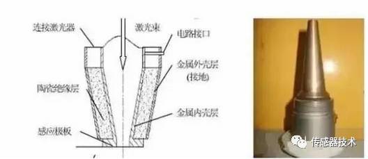
The laser head uses a displacement capacitive sensor combined with the nozzle body, where the sensor consists of two different metallic conical shells, one inside the other. The middle layer between the inner and outer shells is a ceramic insulating medium, and the outer shell is grounded and insulated from the inner layer, acting as a shielding layer during operation. The conical tip of the inner shell connects to an annular metal piece insulated from the outer layer, which together with the metal workpiece forms the two plates of a capacitive sensor. A channel is drawn from the inner shell to connect to the signal acquisition system, allowing the sensor to operate by charging the emission plate (annular metal piece) through the inner metal shell, with the entire probe connected to the laser processing machine, and the laser beam emitted through the inner metal shell during operation.
During the laser cutting process, the nozzle equipped with displacement sensors maintains a consistent gap to the workpiece, ensuring the quality of the cutting.
Application of Displacement Sensors in Road Transport Overload Detection
To address the issue of vehicle overload, specific measures are taken, such as setting up vehicle overload detection devices at highway toll booths. The existing devices are weighing devices used to test whether a vehicle’s load is overweight, but drivers often cannot accurately stop their vehicles at the center of gravity of the weighing device when paying tolls, leading to inaccurate weight readings.
Vehicle overload detection devices based on photoelectric displacement sensors are designed to detect overloads and trigger alarms from the source. They can determine the load condition of a vehicle by measuring the distance between the chassis and the axle.
This system includes at least one displacement sensor installed on the chassis, a vehicle controller, an alarm circuit, and an electromagnetic wave emission module. The displacement sensor measures the distance between the chassis and the axle; the vehicle controller receives the signal from the displacement sensor, processes it, and outputs control signals; the electromagnetic wave emission module can emit electromagnetic wave signals, etc.
Today, various displacement sensors are developing towards high speed, high precision, multifunctionality, multi-parameter, and small size, and have been accepted by military, industrial, and agricultural markets. They are widely used in machinery, power, power plants, aerospace, metallurgy, coal, petroleum, railways, transportation, light industry, textiles, building materials, water conservancy, and other industries for automatic measurement and control in mining enterprises, research institutes, colleges and universities, and military product development and application.