Click the blue text to follow us
Sometimes we follow too many public account messages and miss some of the messages we like, unable to see the Industrial Control Forum’s push in time. We can star or pin the public account. So how to star and pin it? [Open an article from the Industrial Control Forum public account, click the blue text under the article title to enter the Industrial Control Forum public account, in the upper right corner “···” select set as star, pin the public account] Click the blue text to follow us
One
System Overview:
A certain workshop of Shanghai Baosteel uses the Mitsubishi FX3U series PLC to expand FX3U-485-BD and FX3U-485ADP-MB along with several temperature collection modules to realize Modbus communication and collect 10 temperature signals on site. The upper computer of the first phase uses C#.NET and the PLC programming port to achieve programming port protocol communication to display the real-time measurement values of 10 temperature readings and other data monitoring.
The second phase of the equipment controller uses Siemens S7-200 series PLC, where the upper computer of the second phase uses C#.NET and the PLC’s Port1 communication port to achieve PPI protocol communication to display the real-time measurement values of the second phase temperature and other data monitoring. The PLC’s Port0 port and Delta VFD-M series inverter achieve Modbus RTU protocol communication.
Now it is required that the second phase must simultaneously collect the 10 temperature measurement values of the first phase. Since the second phase controller Siemens S7-200’s Port0 has already established Modbus RTU master station communication with the Delta VFD-M inverter, the first phase controller Mitsubishi FX3U can only use FX3U-485-BD communication hardware, and the software uses RS instruction without protocol programming to implement Modbus RTU slave.
Two
Siemens S7-200 Communication Programming:
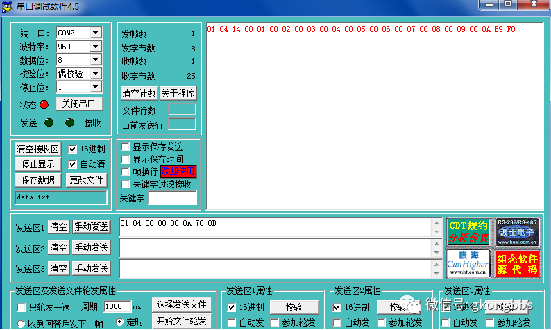
The communication parameters of Siemens S7-200’s Port0 communication port are agreed to be 9600, 8, E, 1, the communication protocol is Modbus RTU master station, and the communication physical layer is RS485. The communication function is to periodically read the 10 input registers of the slave, with the agreed slave address being 0x01, function code being 0x04, starting register address being 0x0000, and the number of registers to pre-read being 0x000a. This means that the Siemens S7-200’s Port0 communication port will periodically send the command 01 04 00 00 00 0A 70 0D. Assuming the current 10 temperature readings are 1, 2, 3, 4, 5, 6, 7, 8, 9, 10 degrees, the Mitsubishi FX3U expanded FX3U-485-BD communication port will return the following data after receiving the above command: 01 04 14 00 01 00 02 00 03 00 04 00 05 00 06 00 07 00 08 00 09 00 0A B9 F0
The program for the Modbus RTU master station on Siemens S7-200’s Port0 is shown below:
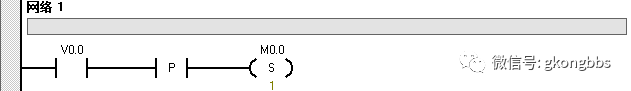
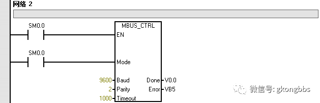
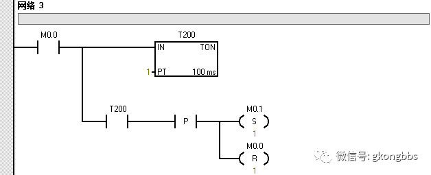
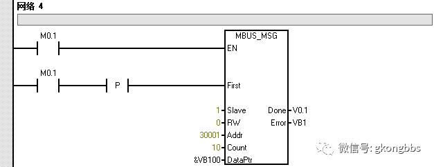
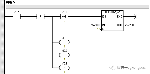
The Siemens S7-200’s Port0 communication port sends the command 01 04 00 00 00 0A 70 0D every 100ms, and the Mitsubishi FX3U expanded FX3U-485-BD communication port will return the 10 temperature measurement values in real-time according to the Modbus RTU protocol after receiving the command. The 10 temperature measurement values read by the Siemens S7-200 will be saved in VW200, VW202, VW204, VW206, VW208, VW210, VW212, VW214, VW216, and VW218, these 10 word registers.
Three
Mitsubishi FX3U Communication Programming:
The communication parameters of the Mitsubishi FX3U expanded FX3U-485-BD communication port are agreed to be 9600, 8, E, 1, the communication protocol is Modbus RTU slave, and the communication physical layer is RS485. The function is to return the 10 temperature measurement values in real-time according to the Modbus RTU protocol after receiving the command from the Modbus RTU master station of Siemens S7-200. The 10 temperature measurement values are stored in registers D0 to D9, and programming is implemented through RS instruction without protocol. Due to space limitations, only a detailed explanation of the Mitsubishi FX3U without protocol programming is provided below.
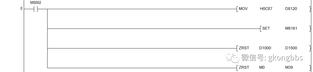
1. The following program sets the PLC’s 485BD communication parameters to 9600, 8, E, 1, the communication physical layer is RS485, 8-bit data processing mode, and clears the relevant registers and relays.
2. The following is the RS instruction program segment, which stipulates that 8 bytes are received and 25 bytes are sent in the communication without protocol. In the Modbus RTU protocol, the 0x04 function code master station command is fixed at 8 bytes, and the master station reads the 10 input registers of the slave. According to the Modbus RTU protocol, the number of bytes returned by the slave is 10*2+5=25 bytes.

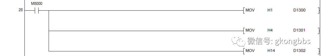
3. The following program specifies the slave address, function code, and byte count in the returned data from the Mitsubishi PLC. Register D1300 is the slave address, D1301 is the function code, and D1302 is the byte count.
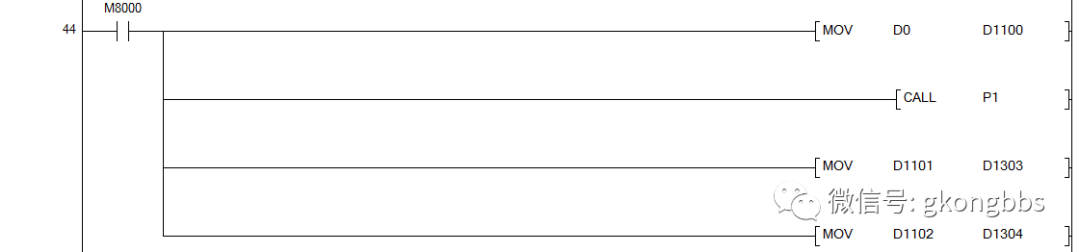
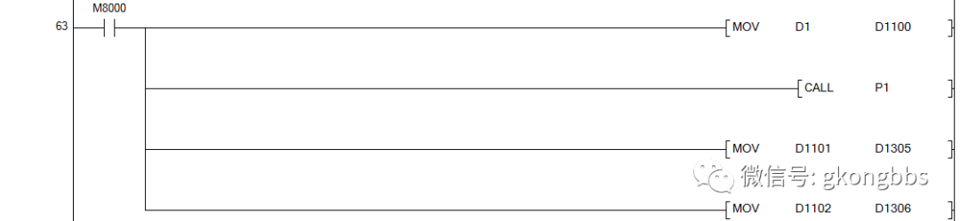
4. The following program handles the first temperature measurement value. The first temperature measurement value is stored in D0, which is sent to the P1 subroutine’s entry parameter D1100. After calling the P1 program, the exit parameters D1101 and D1102 of the P1 subroutine are sent to D1303 and D1304, which means D1303 and D1304 store the high and low 8 bits of D0 respectively.
5. The following program handles the second temperature measurement value. The second temperature measurement value is stored in D1, which is sent to the P1 subroutine’s entry parameter D1100. After calling the P1 program, the exit parameters D1101 and D1102 of the P1 subroutine are sent to D1305 and D1306, which means D1305 and D1306 store the high and low 8 bits of D1 respectively.
6. The following program handles the third temperature measurement value. The third temperature measurement value is stored in D2, which is sent to the P1 subroutine’s entry parameter D1100. After calling the P1 program, the exit parameters D1101 and D1102 of the P1 subroutine are sent to D1307 and D1308, which means D1307 and D1308 store the high and low 8 bits of D2 respectively.

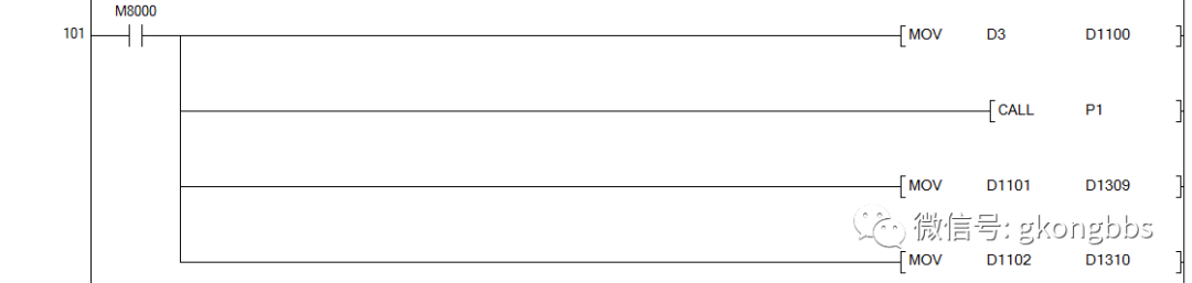
7. The following program handles the fourth temperature measurement value. The fourth temperature measurement value is stored in D3, which is sent to the P1 subroutine’s entry parameter D1100. After calling the P1 program, the exit parameters D1101 and D1102 of the P1 subroutine are sent to D1309 and D1310, which means D1309 and D1310 store the high and low 8 bits of D3 respectively.
8. The following program handles the fifth temperature measurement value. The fifth temperature measurement value is stored in D4, which is sent to the P1 subroutine’s entry parameter D1100. After calling the P1 program, the exit parameters D1101 and D1102 of the P1 subroutine are sent to D1311 and D1312, which means D1311 and D1312 store the high and low 8 bits of D4 respectively.

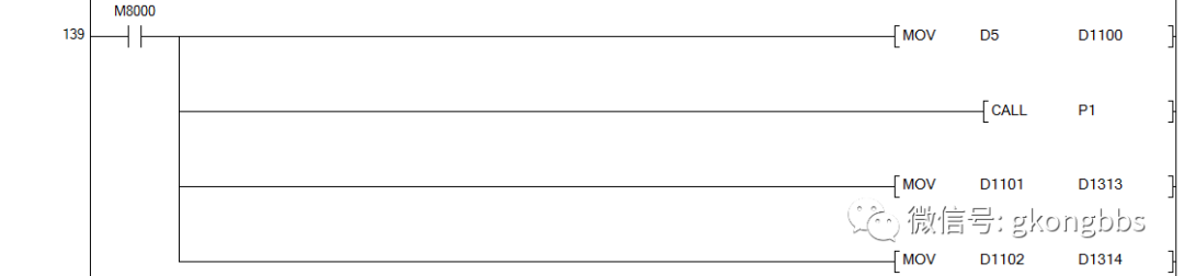
9. The following program handles the sixth temperature measurement value. The sixth temperature measurement value is stored in D5, which is sent to the P1 subroutine’s entry parameter D1100. After calling the P1 program, the exit parameters D1101 and D1102 of the P1 subroutine are sent to D1313 and D1314, which means D1313 and D1314 store the high and low 8 bits of D5 respectively.
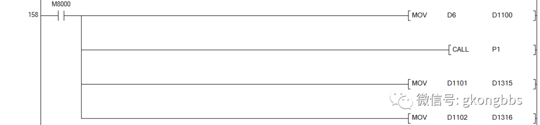
10. The following program handles the seventh temperature measurement value. The seventh temperature measurement value is stored in D6, which is sent to the P1 subroutine’s entry parameter D1100. After calling the P1 program, the exit parameters D1101 and D1102 of the P1 subroutine are sent to D1315 and D1316, which means D1315 and D1316 store the high and low 8 bits of D6 respectively.
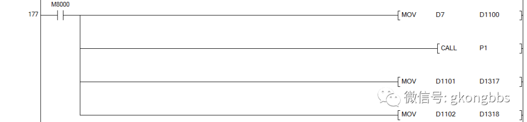
11. The following program handles the eighth temperature measurement value. The eighth temperature measurement value is stored in D7, which is sent to the P1 subroutine’s entry parameter D1100. After calling the P1 program, the exit parameters D1101 and D1102 of the P1 subroutine are sent to D1317 and D1318, which means D1317 and D1318 store the high and low 8 bits of D7 respectively.
12. The following program handles the ninth temperature measurement value. The ninth temperature measurement value is stored in D8, which is sent to the P1 subroutine’s entry parameter D1100. After calling the P1 program, the exit parameters D1101 and D1102 of the P1 subroutine are sent to D1319 and D1320, which means D1319 and D1320 store the high and low 8 bits of D8 respectively.

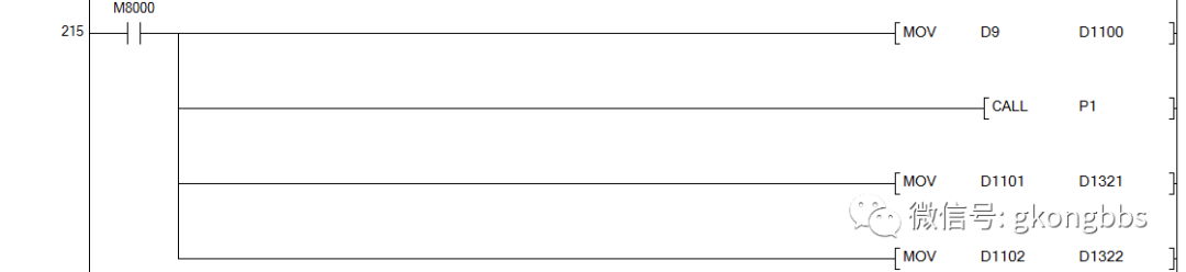
13. The following program handles the tenth temperature measurement value. The tenth temperature measurement value is stored in D9, which is sent to the P1 subroutine’s entry parameter D1100. After calling the P1 program, the exit parameters D1101 and D1102 of the P1 subroutine are sent to D1321 and D1322, which means D1321 and D1322 store the high and low 8 bits of D9 respectively.
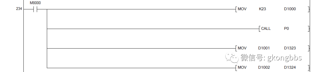
14. The CRC check program command segment is here calling the P0 program, the P0 subroutine’s entry parameter is D1000, which is the number of bytes participating in CRC check, D1300 is the first participating data for CRC check, and the exit parameters are D1001 and D1002, which are the low and high 8 bits of CRC check, and the final CRC check is sent to D1323 and D1324.
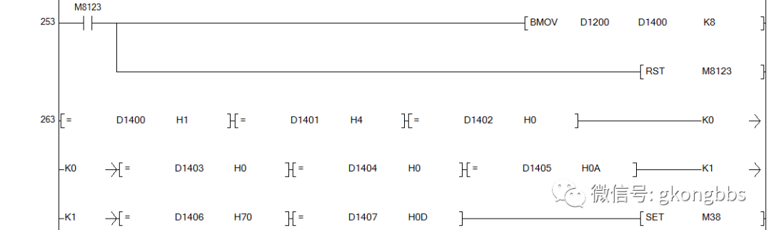
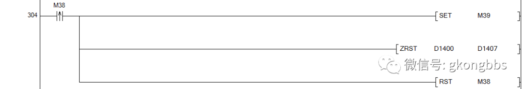
15. The receive completion program command segment transfers the received data to D1400~D1407 after receiving is complete. It then checks if the received data meets the Modbus RTU master station command 01 04 00 00 00 0A 70 0D. If it does, it indicates that the received command is indeed the master station reading the command for the 10 temperature measurement values. At this point, M38 is set, M38 rising edge sets M39, while clearing the D1400~D1407 receive storage area and resetting M38, completing the receive processing.
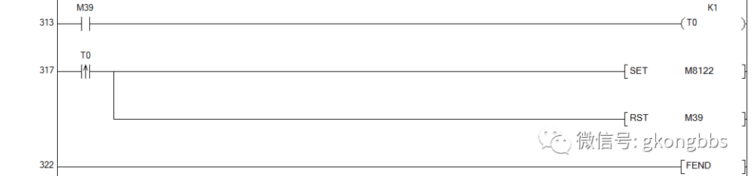
16. The start sending program command segment shows that D1300~D1324 save the returned data, where D1300 is the slave address, D1301 is the function code, D1302 is the byte count, D1303~D1322 save the high and low 8 bits of the 10 temperature measurement values, and D1323 and D1324 save the CRC check. After M39 is set, a delay starts, and when the delay time is reached, the RS instruction is sent to start sending, completing the sending.
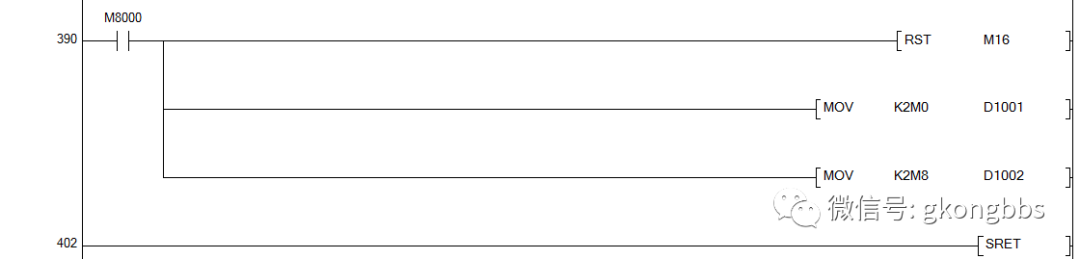
17. The P0 subroutine’s function is to calculate the CRC check, occupying resources: M0-M15, M16, M17, M18, V0, Z0, with the entry parameter being D1000, which is the number of bytes participating in CRC check, D1300 is the first participating data for CRC check, and the exit parameters are D1001 and D1002, which are the low and high 8 bits of CRC check, and the final CRC check is sent to D1323 and D1324.
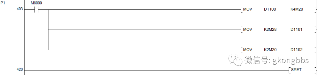
18. The P1 subroutine’s function is to split the high and low 8 bits of a certain register, occupying resources: M20-M35, with the entry parameter being D1100, which is the register to be split, and the exit parameters are D1101 and D1102, which are the high and low 8 bits of the split register.
Four
Communication Program Testing:
1. Mitsubishi PLC communication program testing: The serial port debugging assistant sends the command 01 04 00 00 00 0A 70 0D, and the Mitsubishi PLC returns the command 01 04 14 00 01 00 02 00 03 00 04 00 05 00 06 00 07 00 08 00 09 00 0A B9 F0 after receiving the command. After analysis, the sending is correct, and the return is correct, indicating that the Mitsubishi PLC program is correct.
2. Siemens PLC communication program testing: Through the serial port debugging assistant monitoring, the PLC will periodically send the command 01 04 00 00 00 0A 70 0D, indicating that the PLC sends the command correctly.
3. System joint debugging: The Siemens PLC’s Port0 communication port and Mitsubishi FX3U-485-BD hardware are connected. After running the Mitsubishi PLC, and then running the Siemens PLC, the result shows that the VW200~VW218 of the Siemens PLC can read the 10 temperature measurement values from D0~D9 of the Mitsubishi PLC in real-time, indicating successful communication.
Source/China Industrial Control Network, please contact for reprint
Previous Recommendations

Share the ball

Like the ball

Watching the ball