When learning about the Internet of Things, the first thing that comes to mind is the ESP8266. This module can connect to the internet, allowing it to connect to your home router or act as a hotspot for your phone to connect to. Isn’t that fascinating? Although the programming and related products for this device are quite mature, some beginners still don’t know how to get started. How can you use an ESP8266 along with an STM32 microcontroller to create a small product? What is the learning path like, and how can one get started?
I suggest the following steps: 1. First, learn about the ESP8266 module on its own and understand its AT command set. Use a serial debugging tool and a network debugging tool to get familiar with this module. 2. Learn about the MQTT protocol. Why is it important to learn the MQTT protocol as the second step? Because our ESP8266 will connect to a server, and simply put, MQTT is the communication protocol between the ESP8266 and the server. This protocol is not difficult; I have written notes that can be published directly on this public account later. 3. Learn to use Android Studio to create your own app. Since this is about IoT control, there must be an app. Although Alibaba Cloud and Smart Cloud have ready-to-use apps, as an electronics enthusiast, you shouldn’t limit yourself to cloud intelligence; it’s impressive to create your own app! This project will guide you to use STM32 and ESP8266 to create something like a temperature and humidity display, which can be viewed in a mobile app in real-time.
Learning methods: 1. Go to major forums to find information and look for relevant videos on Bilibili. 2. Learn to apply what you’ve learned; if you can light up an LED, you should also be able to turn it off. 3. Get hands-on experience; programming is not just about writing code, but also about debugging and modifying it.
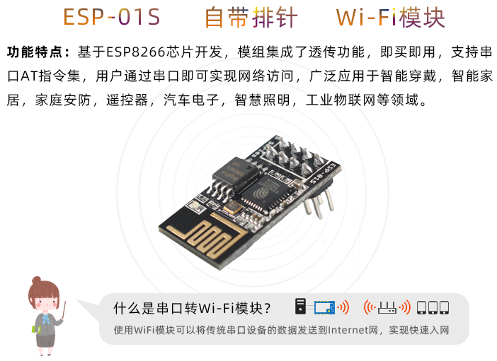
Introduction to ESP8266 01S
Before using the AT functionality, the module must have the AT firmware. Each module manufacturer may modify and reduce the official AT firmware from Espressif, but the core AT command functions remain the same. The ESP8266 modules we buy usually come with pre-installed firmware, so there’s no need to flash firmware ourselves.
The link below shows the ESP8266 available for 13.49 RMB.
The ESP-01S WiFi module is a low-power, cost-effective embedded wireless networking control module. It can meet the demands of IoT applications such as smart grids, building automation, security, smart homes, and remote medical care. The core processor of the module, ESP8266, integrates the industry-leading Tensilica L106 ultra-low-power 32-bit microcontroller in a small package, supporting a main frequency of 80MHz and 160MHz, and supports RTOS with an onboard antenna. The module supports a complete TCP/IP protocol stack. Users can use this module to add networking capabilities to existing devices or build independent network controllers.
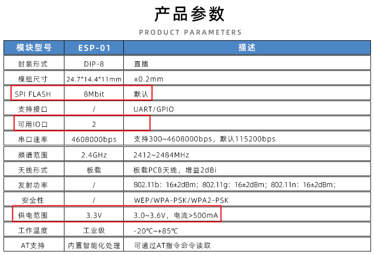
(1) The module power supply voltage is DC 3.3V, with a current of 500mA or more; (2) The maximum output current of the Wi-Fi module IO is 12mA; (3) The NRST pin of the Wi-Fi module is active low; the EN enable pin is active high; (4) To enter the upgrade mode of the Wi-Fi module: GPIO0 is low, then reset the module; to enter normal working mode: GPIO0 is high, then reset the module; (5) The RXD of the Wi-Fi module connects to the TXD of the external MCU, and the TXD of the Wi-Fi module connects to the RXD of the external MCU;
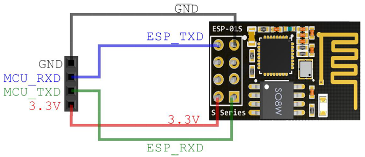
Flashing Firmware on ESP8266
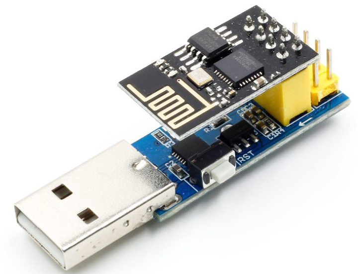
You can flash the firmware using DuPont wires or a firmware flashing module (which can be bought cheaply on Taobao), as shown below:
Controlling the ESP8266 Module with AT Commands
The official AT commands from Espressif have nearly 100 commands, but only a dozen are commonly used and easy to understand. Here are some examples of commonly used commands, along with step-by-step instructions to connect to a remote server via TCP to send and receive data. For more AT commands, refer to the “ESP8266 AT Command Set Manual”.
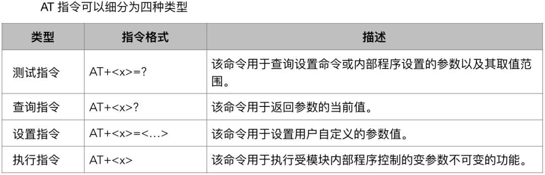
In summary, the structure of AT commands is that each command starts with AT, followed by the parameters to query (read) or set (write). For example, the command to query the Wi-Fi mode is AT+CWMODE?, and to set the Wi-Fi mode is AT+CWMODE=3. Additionally, a carriage return and line feed must be appended at the end of the data to be sent, which is hexadecimal 0x0D 0x0A. Note: When sending AT commands using a serial debugging tool, you only need to add a carriage return at the end of the command. You can check the “Send in Hex” option to observe whether 0x0D 0x0A is appended at the end of the data.
1. Testing If the Module is Working Normally
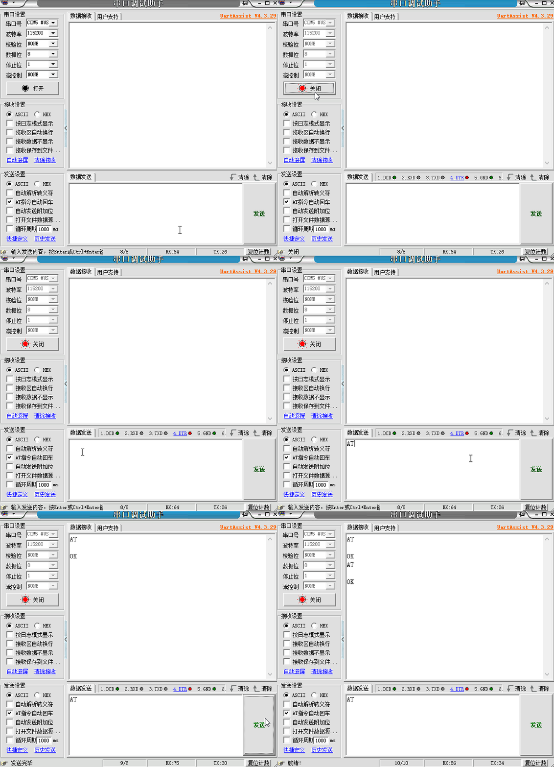
This command is usually used after powering on to check if the module has started normally. If it replies OK, then it has started normally.
2. Enable/Disable Echo
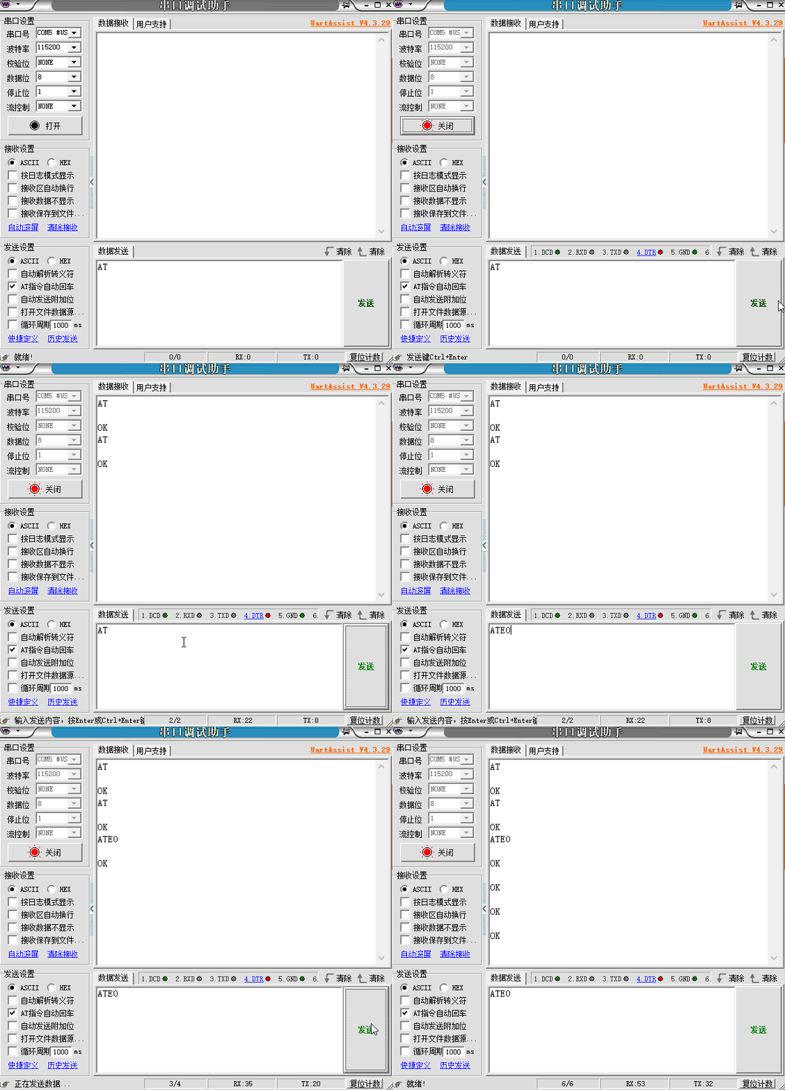
As shown in the above image, we sent an AT command, and the module replied with AT OK, meaning the module echoed back the command it received before sending a valid reply. This echo is called echoing. After disabling echo (sending ATE0), if we send AT again, it will only reply with OK. See the image below:
3. Setting AP Mode and AP Parameters
There are two Wi-Fi modes: one is called AP mode and the other is Station mode. AP stands for Access Point, which we usually refer to as a hotspot, such as a Wi-Fi router, a mobile phone with hotspot enabled, or public hotspots. These AP devices allow other devices (like phones and laptops) to connect after entering the hotspot name and password (which can also be left empty). Station mode is for devices that connect to the AP, such as phones and laptops. When the ESP8266 is set to AP mode, other devices can connect to this hotspot, supporting up to 4 Station devices. AP mode is also the default mode for the ESP8266. The process to set up the ESP8266 is as follows:
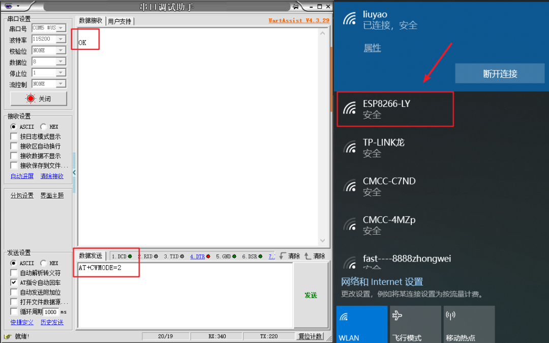
1. First, send AT+CWMODE? to query which mode the module is currently in. As shown in the image below, AT+CWMODE=2 indicates hotspot mode.
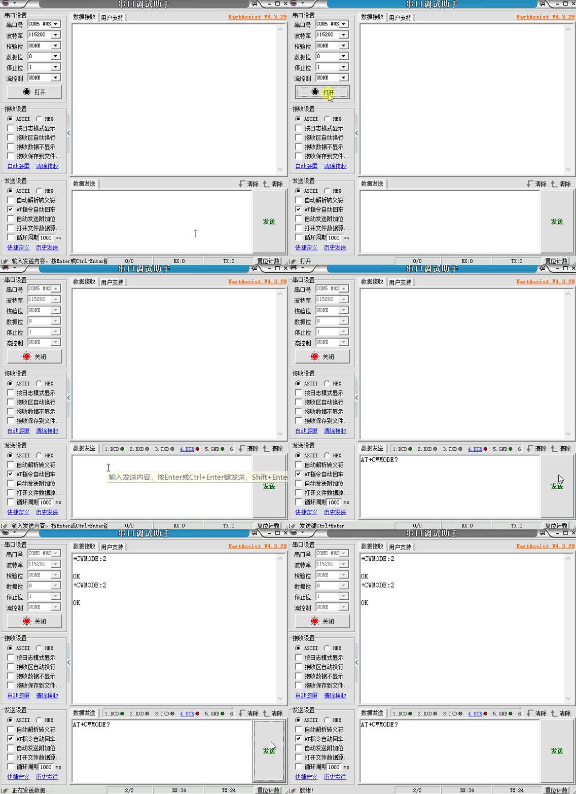
2. Next, we send AT+CWMODE=2 to set the module to hotspot mode, and our computer will display the hotspot name.
3. Now we will customize the hotspot name and password for our ESP8266 to see if our computer can connect to the ESP8266 module we set up.
1. Set the Wi-Fi mode to AP mode
2. Set AP hotspot properties
AT+CWSAP=AT+CWSAP_DEF=”ESP8266-XSD”,”12345678″,5,3
This means: the hotspot name is ESP8266-XSD, the password is 12345678, using channel 5, and the encryption method is WPA2_PSK. The channel corresponds to different radio frequencies; if there are Wi-Fi signals with the same channel in the same space, it will cause interference and affect internet quality. Therefore, channels can be set to avoid such interference. Commonly used channels are 1, 6, and 11, as these three channels do not interfere with each other. The effect of the settings is shown in the image below:
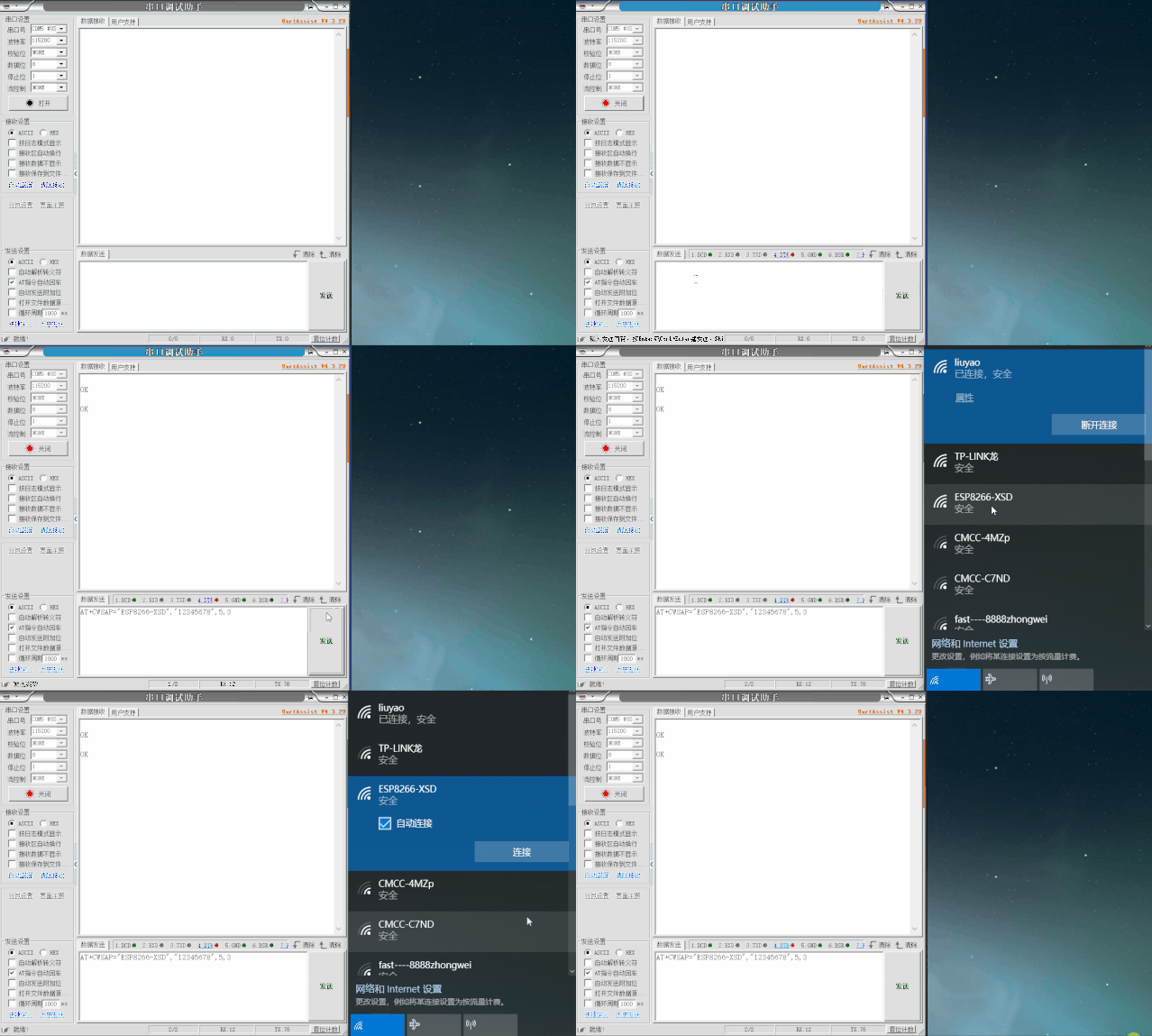
The connection limit can restrict the number of Station devices that can connect. Broadcasting or not broadcasting the SSID refers to whether to hide the hotspot name, making the hotspot more secure. Additionally, AT+CWSAP=AT+CWSAP_DEF indicates that the parameters set will be stored in flash memory, while another similar command AT+CWSAP=AT+CWSAP_CUR indicates that the parameters set will become invalid after a reboot, meaning they will not be saved to flash. Other AT commands also have similar suffixes.
4. Setting to Station Mode
This mode is the most commonly used because IoT devices need to connect to the home router to access the internet. At this point, the device acts as a Station connecting to the AP hotspot. The process to set the Station and connect to the AP is as follows:
1. Set the Wi-Fi mode to Station 2. Connect to the home router
AT+CWJAP=”liuyao”,”liuyao1001″
The image below shows the serial output during the connection process: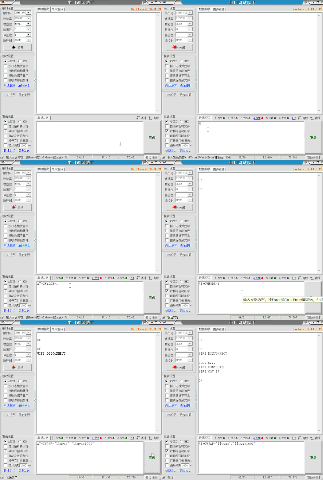 At this point, we can see that our ESP8266 module is connected to the home router. If we want to disconnect, we can use AT+CWQAP to disconnect the ESP8266 from the router.
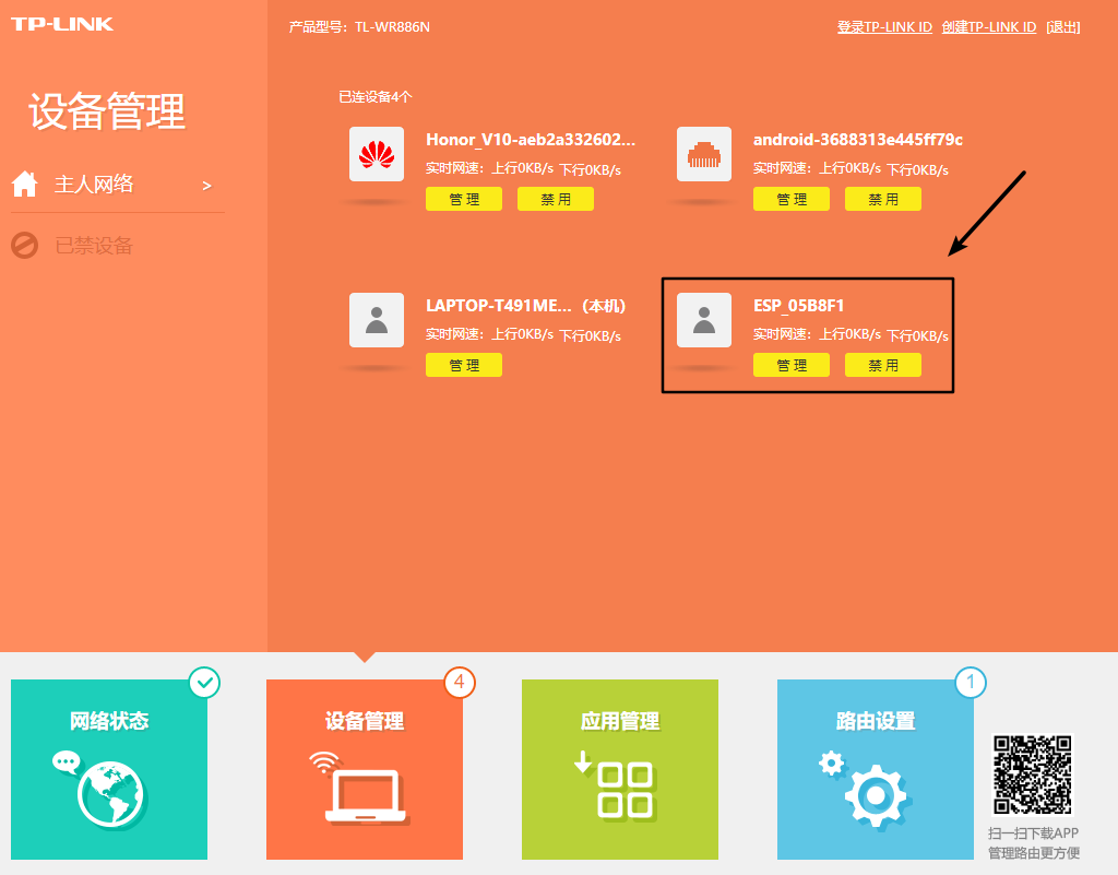
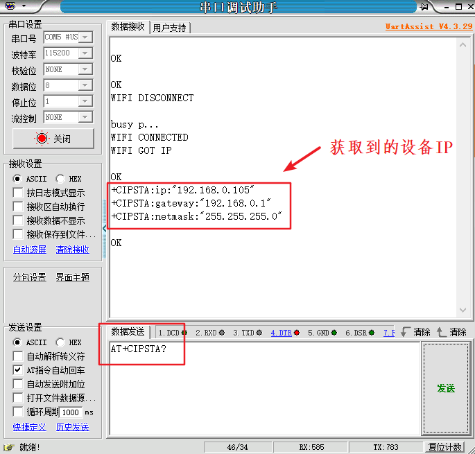
Now our ESP8266 is connected to the home router. If we want to get the IP address assigned to this ESP8266, we can use the command AT+CIPSTA?, which returns the local IP address assigned by the router to the ESP8266, as well as the gateway address and subnet mask.
5. Using TCP for Local Device Communication
Establishing a TCP Connection (AT+CIPSTART)
To achieve local device communication using TCP, the ESP8266 must first connect to the home hotspot. This command can specify the type of protocol to establish the connection, typically TCP or UDP. We first open the network debugging tool and set it as a TCP server, as shown below: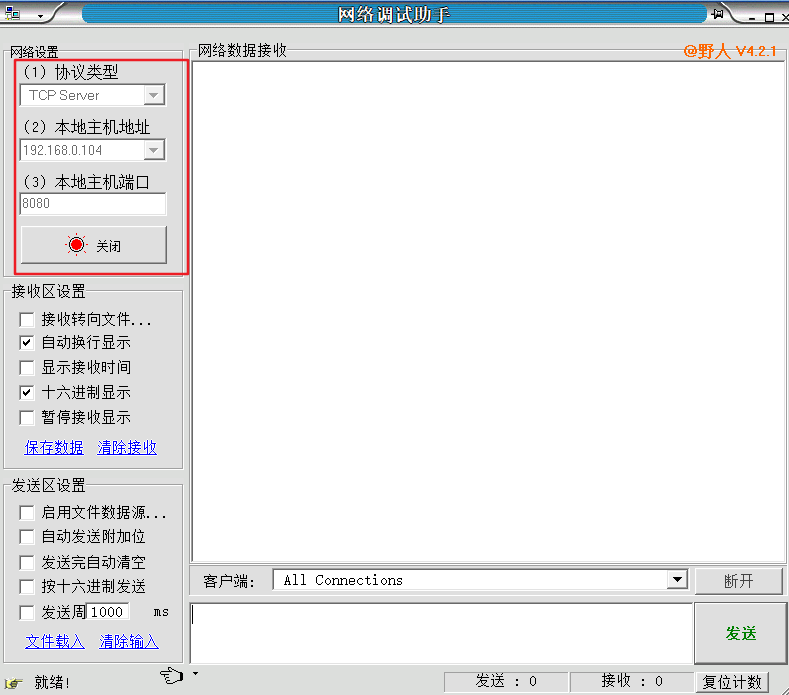 Next, send the AT command to establish a TCP connection. A successful connection will prompt CONNECT, and then use the command: AT+CIPSEND=14, where 15 is the length of the data to be sent. After this command is completed, the receiving window will display >, and we can send “I’m TCP Client” in the sending window. The TCP server will receive this information, and then the TCP server will send “I’m TCP Server” back, which will be printed on the serial receiving end. Below is the process of the ESP8266 connecting to the current environment’s hotspot and establishing a TCP connection to transmit data, where all characters and punctuation must be in English.
1. Set Wi-Fi mode to Station: AT+CWMODE=1
2. Connect to home router: AT+CWJAP=”liuyao”,”liuyao1001″
3. TCP: AT+CIPSTART=”TCP”,”192.168.0.103″,8080
4. Prompt to send data length of 14: AT+CIPSEND=14
5. Serial debugging tool sends: I’m TCP Client
6. Network debugging tool sends: I’m TCP Server
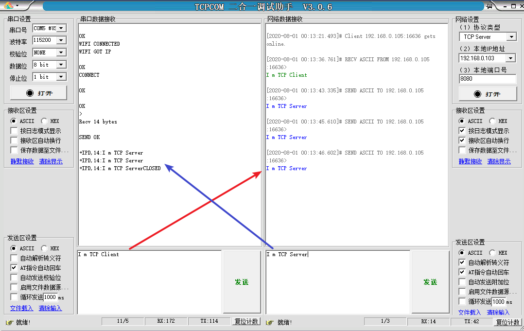
Many people may be confused at this step, not knowing why this is necessary. You might wonder what the serial debugging tool and network debugging tool are, and what TCP server means. Haha, I believe many beginners are not clear about this at this point. Let me briefly explain: we want the ESP8266 to connect to the home network, so the network debugging tool’s TCP server is the network we want to connect to. But if you’re connecting to your home network, how do you send data to your home router? How do you know the router has received the data? How does the router send data back to you? The purpose of using the network debugging tool is to replace the router in the local area network. The TCP server means the server side. As for why we use the serial debugging tool, I don’t need to explain; only by debugging the relevant data on the serial debugging tool can we use the microcontroller’s serial interface combined with the ESP8266 to replace the client, and then we won’t need the debugging tool anymore.
So, we must ensure that we debug the relevant data on the serial debugging tool, understand the principles and processes, and then proceed to work on the microcontroller program and build your server instead of using the network debugging tool as a substitute. Now do you understand?
Enabling Transparent Transmission (AT+CIPMODE=1)
Earlier, when sending data using TCP, we had to specify the length of the data to be sent before each transmission. Additionally, after receiving data, there would be a prefix of +IPD,< len >, which is inconvenient for data processing. Therefore, we can use the command AT+CIPMODE=1 to enable transparent transmission mode. After enabling this mode, we only need to use AT+CIPSEND to inform the ESP8266 to start transparent transmission, and then we can directly send the desired data. When receiving data, there will be no prefix of +IPD,< len >.Below is the process of the ESP8266 connecting to the current environment’s hotspot, establishing a TCP connection, and enabling transparent mode for data transmission, where all characters and punctuation must be in English.
1. Set Wi-Fi mode to Station: AT+CWMODE=1
2. Connect to home router: AT+CWJAP=”liuyao”,”liuyao1001″
3. TCP: AT+CIPSTART=”TCP”,”192.168.0.103″,8080
4. Enable transparent mode: AT+CIPMODE=1
5. Start transparent transmission: AT+CIPSEND
6. Serial debugging tool sends: hello I’m TCP Client!
7. Network debugging tool sends: hello I’m TCP Server!
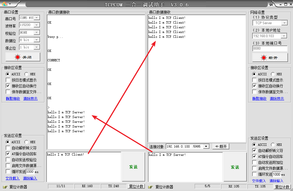
If you want to exit transparent transmission mode, send +++ (0x2B 0x2B 0x2B), noting that there are no line breaks. Then use the command AT+CIPMODE=0 to exit transparent mode and revert to the default transmission mode. If you do not exit transparent mode, you cannot send AT commands in transparent mode; it will default to sending as a string.
6. Using SmartConfig for Device Network Configuration
Earlier, we used the command AT+CWJAP to actively connect to the home Wi-Fi. However, in most IoT products, there is a lack of input devices for entering Wi-Fi passwords, such as keyboards, and it is even more impractical to give users the program to modify the Wi-Fi hotspot name and password at home. In actual project development, the most commonly used method is to enable a device to enter a certain mode with a button and use a smartphone to inform the device of the current Wi-Fi password for network configuration. This mode is called SmartConfig. In this mode, the ESP8266 listens for UDP broadcast packets on a specified port. If it receives a broadcast packet in the required format, it will parse it to obtain the Wi-Fi SSID and password and then automatically connect to the obtained Wi-Fi hotspot, achieving one-click network configuration.
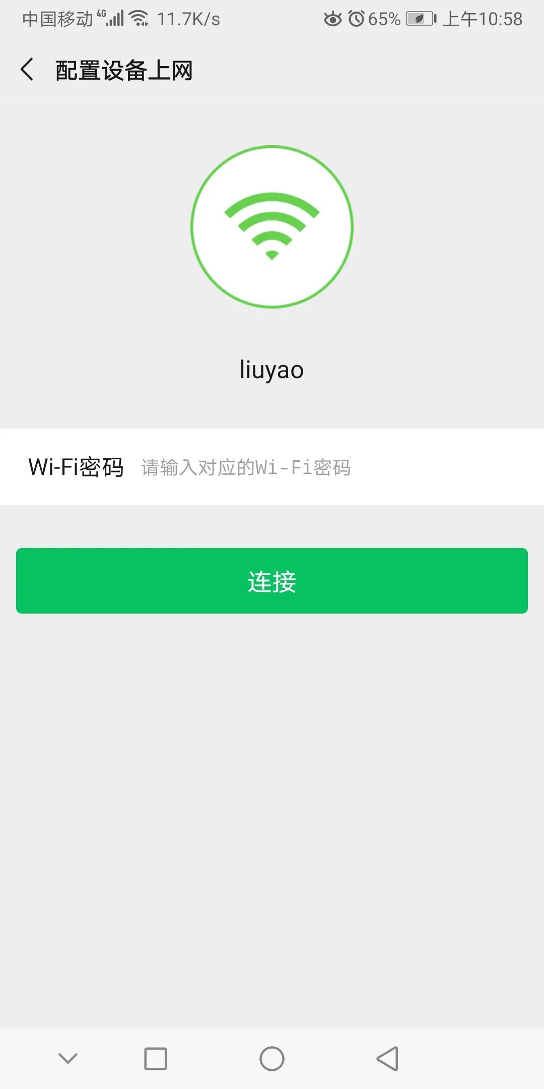
Smart configuration requires three devices: the home router, the Wi-Fi module, and a smartphone. The module is in station mode, and the smartphone is connected to the home Wi-Fi. The working principle is: we need to set the Wi-Fi to station mode because the default is AP mode, and ensure that the smartphone is connected to the home router hotspot.
The first line on the phone indicates the hotspot name to which the phone is currently connected. Below, the user needs to manually input the password corresponding to the router hotspot, and there will be a button labeled “Configure Network” (Connect). When the user clicks this button, the phone will broadcast via UDP to a certain port or IP address. The broadcast content is a data frame structure encapsulated by the manufacturer, and during the broadcast, there is no need to specify a specific IP address; each module may have a different default. Just specify the account, and when the user presses the configure network button, the Wi-Fi module will enter the SmartConfig mode.At this point, the Wi-Fi module will be in a listening state, for example, listening for UDP on port 8080. If it receives valid data, it will extract the useful hotspot name and password from it and use a function similar to transparent mode to connect to the specified hotspot, thus achieving one-click network configuration.

Can the King of IoT, ESP-32, outperform STM32?
PCB design for eight-layer boards, analysis of computer motherboard design
Programming is fun, but you must understand open source licenses~
Serial communication in microcontrollers is simple and easy to understand