If you are interested in sensors, you may be familiar with proximity detection sensors. There are various sensors available for proximity detection, each with its own features and limitations.
One method is to use an infrared transceiver. These sensors measure the time it takes for an infrared beam to travel back and forth and calculate the distance between the sensor and the target surface.
In this post, we will introduce the TMD27713 distance detection sensor. Whether you are a beginner or an experienced individual, this article will help you understand the TMD27713 sensor step by step.
Required Components
● TMD27713 IRLED + ALS + Proximity Sensor Module
● Arduino UNO R3 Development Board
● Male-to-female jumper wires
Introduction to the TMD27713 Sensor
The TMD27713 chip is a proximity detection sensor based on infrared beams. We can also use its receiver to detect ambient light intensity. This chip includes a digital proximity sensor, an LED driver, and an infrared LED, all integrated together without the need for calibration.
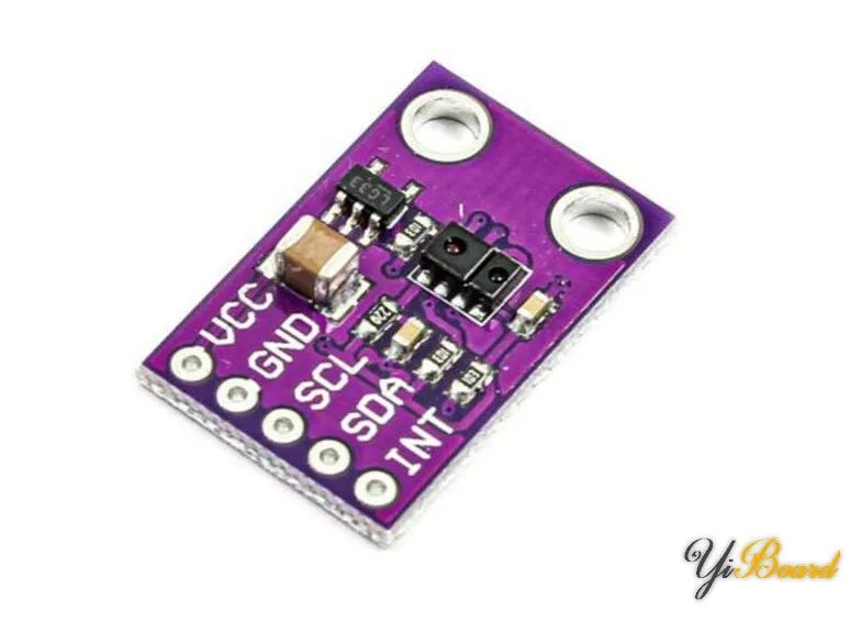
Additionally, this chip can eliminate background light, allowing it to work under various conditions, from very bright environments to dark rooms. It also has a wide dynamic range suitable for short-distance detection. Furthermore, the chip uses micro-optical lenses to more effectively transmit and receive infrared energy.
Pin Configuration of the TMD27713 Module
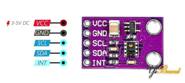
The module has a total of 5 pins, as shown in the figure below.
Hardware Connection of the TMD27713 Sensor Module to the Arduino Development Board
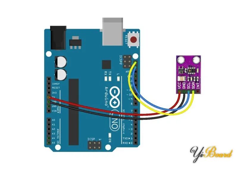
Now, let’s see how to measure distance using the TMD27713 sensor and Arduino. Connect the TMD27713 module to the Arduino development board as shown in the figure below.
Example Code
Copy the following code into the Arduino IDE software and upload it to your development board.
#include <Wire.h>
// TMD2771 I2C address is 39(57)#define Addr 0x39
void setup(){  // Initialise I2C communication as MASTER  Wire.begin();  // Initialise Serial Communication, set baud rate = 9600  Serial.begin(9600);
  Wire.beginTransmission(Addr); // Start I2C Transmission  Wire.write(0x00 | 0xA0); // Select enable register
  Wire.write(0x0F); // Set power on, proximity and ALS enabled  Wire.endTransmission();// Stop I2C Transmission

  Wire.beginTransmission(Addr); // Start I2C Transmission  Wire.write(0x01 | 0xA0); // Select ALS time register  Wire.write(0xDB); // Atime = 101 ms  Wire.endTransmission();  // Stop I2C Transmission

  Wire.beginTransmission(Addr); // Start I2C Transmission    Wire.write(0x02 | 0xA0); // Select proximity time register    Wire.write(0xFF); // Ptime = 2.72 ms    Wire.endTransmission();// Stop I2C Transmission
  Wire.beginTransmission(Addr); // Start I2C Transmission  Wire.write(0x03 | 0xA0); // Select Wait time register  Wire.write(0xFF); // Wtime = 2.72 ms  Wire.endTransmission();// Stop I2C Transmission

  Wire.beginTransmission(Addr); // Start I2C Transmission  Wire.write(0x0E | 0xA0); // Select pulse count register  Wire.write(0x04); // Pulse count = 4  Wire.endTransmission();// Stop I2C Transmission

  Wire.beginTransmission(Addr); // Start I2C Transmission    Wire.write(0x0F | 0xA0); // Select control register  // 120 mA LED strength, Proximtiy uses CH1 diode, 1x PGAIN, 1x AGAIN  Wire.write(0x20);    Wire.endTransmission();// Stop I2C Transmission  delay(800);  }
void loop(){  unsigned int data[6];

  Wire.beginTransmission(Addr); // Start I2C Transmission    Wire.write(0x14 | 0xA0); // Select data register    Wire.endTransmission();// Stop I2C Transmission
  // Request 6 bytes of data  Wire.requestFrom(Addr, 6);
  // Read 6 bytes of data  // c0Data lsb, c0Data msb, c1Data lsb, c1Data msb, proximity lsb, proximity msb  if(Wire.available() == 6)  {    data[0] = Wire.read();    data[1] = Wire.read();    data[2] = Wire.read();    data[3] = Wire.read();    data[4] = Wire.read();    data[5] = Wire.read();  }
  // Convert the data  int c0Data = (data[1] * 256) + data[0];  int c1Data = (data[3] * 256) + data[2];  double proximity = (data[5] * 256.0) + data[4];  float CPL = (101.0) / 24.0;  float luminance1 = (1 * c0Data - 2 * c1Data) / CPL;  float luminance2 = (0.6 * c0Data - 1.00 * c1Data) / CPL;  float luminance = 0.0;
  if((luminance1 > 0) && (luminance1 > luminance2))  {    luminance = luminance1;  }  else if((luminance2 > 0) && (luminance2 > luminance1))  {    luminance = luminance2;  }
  // Output data to serial monitor  Serial.print("Ambient Light luminance : ");  Serial.print(luminance);  Serial.println(" lux");  Serial.print("Proximity of the device : ");  Serial.println(proximity);  delay(1000);}
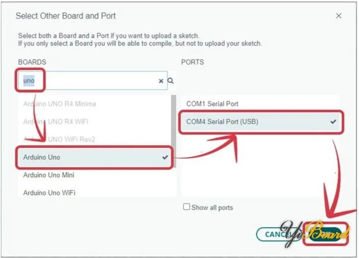
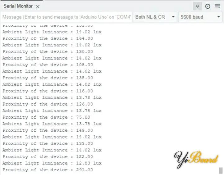
After uploading the code, select the serial port and board type, then open the serial monitor. Keep the baud rate set to 9600.
As you can see, the module sends the brightness level and distance to the serial port. Move an obstacle closer to or further away from the module, and you can observe the change in distance. Based on the adjustments we made to the TMD27713 module in the code, the minimum detectable distance is 4 centimeters.
This is how to connect the TMD27713 sensor module to the Arduino development board. If you have any questions, feel free to reply below.
For more content, please click on “Read the original text” 》》