This article is from a community submission, Author: Wang Yucheng, ML&IoT Google Developers Expert, Chief Engineer at Wenzhou University Smart Lock Research Institute.Learn more: https://blog.csdn.net/wfing
Hello World — The Place Where Dreams Begin (Part 2)
In the previous preparations, we completed model training and converted the model’s binary format into an array recognizable by C++. However, this is just a small step in the microcontroller project. There is still much work to be done.
The code in the project is developed entirely based on the C++11 standard version, avoiding complex logic. This code can also serve as a C++ template for development. But don’t be afraid of C++; in this article, we will describe the overall engineering process using existing code.
-
Sensor data collection -
Preprocess the data and send it to the ML interpreter -
ML model predicts the data -
Make final judgments based on the predicted data -
The device responds to the ML inference results and performs necessary actions
Before reading the code, it is best to understand the code flow through some test cases.
With effective test cases, we can see when erroneous code is executed. After writing, tests typically run automatically and continuously verify whether we are still executing the methods we want. In this example, we will load modeling based on test cases and check the model’s inference: verifying whether the model’s predictions meet our expectations. Starting with test code rather than reading code will help us understand the code flow faster.
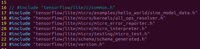
First, let’s take a look at which header files these codes depend on:

The header file structure is as follows:
-
tensorflow/lite/micro/examples/hello_world/sine_model_data.hAt the end of the previous chapter, we used the xxd command to convert the trained model into a C++ binary model
-
tensorflow/lite/micro/kernels/all_ops_resolver.hA class that allows the interpreter to load operations used by the model
-
tensorflow/lite/micro/micro_error_reporter.hA class that can log errors and output them to help with debugging
-
tensorflow/lite/micro/micro_interpreter.hTensorFlow Lite for Microcontrollers interpreter, the model will run in the interpreter
-
tensorflow/lite/micro/testing/micro_test.hA lightweight framework for writing tests; we can run this file as a test
-
tensorflow/lite/schema/schema_generated.hDefines the model of TensorFlow Lite FlatBuffer data structures for understanding the model data in sine_model_data.h
-
tensorflow/lite/version.hThe current version number of the model
After roughly understanding the header file dependencies, we can try to understand the testing process by reading the source code. All the code comes from the hello_world_test.cc file.
We have entered the main body of the code. TensorFlow Lite uses code for the microcontroller testing framework. It looks like this:
TF_LITE_MICRO_TESTS_BEGIN
TF_LITE_MICRO_TEST(LoadModelAndPerformInference) {
...
}
In C++, you can define specially named code blocks, which are called macros. Here, the names are TF_LITE_MICRO_TESTS_BEGIN and TF_LITE_MICRO_TEST macros, which are defined in the micro_test.h file.
These macros wrap the rest of our code in the necessary devices for execution.
We don’t need to know how it works; we only know that we can use these macros as shortcuts to set up tests.
The second macro is named TF_LITE_MICRO_TEST, which accepts a parameter. In this case, the passed parameter is LoadModelAndPerformInference. This statement is the test name, and when running the test, it will be output along with the test results so we can see if the test passed.
// Set up logging
tflite::MicroErrorReporter micro_error_reporter;
tflite::ErrorReporter* error_reporter = µ_error_reporter;
In line 29, we define an instance of MicroErrorReporter. The MicroErrorReporter class is defined in micro_error_reporter.h. It provides a logging mechanism to record information related to the inference process for debugging. We will call it to print debugging information, and then the TensorFlow Lite for Microcontrollers interpreter will use it to print any errors encountered.
You may have noticed the prefix tflite:: in each input name, such as tflite::MicroErrorReporter. This is a namespace, which is just a way to help organize C++ code. TensorFlow Lite defines everything useful under the namespace tflite, meaning if another library happens to implement a class with the same name, they will not conflict with the names provided by TensorFlow Micro.
The first declaration seems simple, but the second looks strange with * and & characters? Why declare an ErrorReporter when we already have MicroErrorReporter?
tflite::ErrorReporter* error_reporter = µ_error_reporter;
To explain what is happening here, we need to understand some background information. MicroErrorReporter is a subclass of ErrorReporter, which provides a way to use this debugging logging mechanism in TensorFlow Lite.
MicroErrorReporter inherits a method from ErrorReporter, replacing it with logic written specifically for use on microcontrollers.
In the previous line of code, we create a variable named error_reporter of type ErrorReporter. It is also a pointer, indicated by the * in its declaration.
A pointer is a special type of variable that does not hold a value but holds a reference. It points to the location in memory where the value can be found. In C++, some specific classes (like ErrorReporter) can point to a value of one of its subclasses (like MicroErrorReporter).
As mentioned earlier, MicroErrorReporter inherits from ErrorReporter. Without going into too much detail, this inheritance method has side effects that make some other methods difficult to understand.
To still access non-overridden methods of ErrorReporter, we need to treat our MicroErrorReporter instance as an ErrorReporter. We do this by creating an ErrorReporter pointer and pointing it to the micro_error_reporter variable. The ampersand (&) in the previous assignment indicates we are assigning the pointer of micro_error_reporter, not its value.
// Map the model into a usable data structure. This doesn't involve any
// copying or parsing, it's a very lightweight operation.
const tflite::Model* model = ::tflite::GetModel(g_sine_model_data);
if (model->version() != TFLITE_SCHEMA_VERSION) {
TF_LITE_REPORT_ERROR(error_reporter,
"Model provided is schema version %d not equal "
"to supported version %d.\n",
model->version(), TFLITE_SCHEMA_VERSION);
}
Through the above code, we obtain the model data array (defined in the file sine_model_data.h) and pass it to a method called GetModel(). This method returns a model pointer, assigned to a variable named model. As you would expect, this variable represents our model.
The Model type is a structure, very similar to a class in C++. The schema_genic.h includes our model’s data and allows us to query information.
Knowledge Point: Data Alignment. If you check the source file of the model in sine_model_data.cc, you will see that the location defining g_sine_model_data references a macro.
DATA_ALIGN_ATTRIBUTE:
const unsigned char g_sine_model_data [] DATA_ALIGN_ATTRIBUTE = {
When data is aligned in memory, processors can read the data most efficiently, meaning the data storage structure can be read in one operation without overlapping the processor boundaries. By specifying this macro, we can ensure that our model data is properly aligned for optimal read performance.
Then, we compare the model’s version number with TFLITE_SCHEMA_VERSION, indicating the version of the TensorFlow Lite library we are currently using. If the numbers match, our model has been converted using a compatible version of the TensorFlow Lite converter.
Tips: Before proceeding to the next step, it’s best to check the model version, as mismatches can lead to strange behaviors that are difficult to debug.
We call the Report() method of error_reporter to log this warning. error_reporter is also a pointer, and we access Report() using the -> operator.
The Report() method is designed to behave similarly to the commonly used printf() in C++, used for logging text. We can use the familiar formatted output from the printf() method in the Report() method.
// This pulls in all the operation implementations we need
tflite::ops::micro::AllOpsResolver resolver;
Our code can log errors, and we have loaded the model into our structure and checked that it is a compatible version.
Next, we create an instance of AllOpsResolver:
Through the above analysis, we understand that the operations of machine learning models are mathematical operations that convert inputs into outputs. The AllOpsResolver class provides all operations for TensorFlow Lite for Microcontrollers and provides the interpreter.
// Create an area of memory to use for input, output, and intermediate arrays.// Finding the minimum value for your model may require some trial and error.
const int tensor_arena_size = 2 * 1024;
uint8_t tensor_arena[tensor_arena_size];
This portion of memory will be used to store the model’s input, output, and intermediate tensors, which we call the tensor arena. In our case, we have provided an array of size 2048 bytes. We specify it as 2×1024. So, how big should our tensor arena be? That’s a good question. Unfortunately, there is no simple answer. Different model architectures have different sizes and quantities of input, output, and intermediate tensors, making it difficult to know how much memory we need. This number does not have to be exact; we can keep the memory within our needs, but since the RAM of microcontrollers is limited, we should keep it as small as possible to leave space for the rest of our program. We can achieve this through trial and error. This is why we express the array size as n×1024: so that we can easily scale the number (by changing n) while keeping it a multiple of eight. To find the correct array size, start high. The highest number used in this book’s examples is 70×1024. Then, reduce the number step by step until the model no longer runs. The last effective number is the correct one!
// Build an interpreter to run the model with
tflite::MicroInterpreter interpreter(model, resolver, tensor_arena,
tensor_arena_size, error_reporter);

// Allocate memory from the tensor_arena for the model's tensors
TF_LITE_MICRO_EXPECT_EQ(interpreter.AllocateTensors(), kTfLiteOk);
First, we declare an interpreter named MicroInterpreter. This class is the core class of TensorFlow Lite for Microcontrollers: a piece of magical code that will model based on the data we provide. We pass most of the objects to its constructor and then call AllocateTensors().
The AllocateTensors() method traverses all tensors defined by the model and allocates memory for them from the tensor_arena. Before trying to run inference, we must call AllocateTensors(); otherwise, inference will fail.
// Obtain a pointer to the model's input tensor
TfLiteTensor* input = interpreter.input(0);
After creating the interpreter, we need to provide some input to the model. At this point, we will write the input data into the model’s input tensor.
To obtain a pointer to the input tensor, we call the input() method of the interpreter. Since a model can have multiple input tensors, we need to pass an index to the input() method to specify which tensor we want. In this case, our model has only one input tensor, so its index is 0. In TensorFlow Lite, tensors are represented by the TfLiteTensor structure, which is defined in c_api_internal.h. This structure provides an API for interacting with tensors. In the next part of the code, we will verify if the tensor is correct. Since we will use tensors extensively, let’s familiarize ourselves with how the TfLiteTensor structure works:
// Make sure the input has the properties we expect
TF_LITE_MICRO_EXPECT_NE(nullptr, input);
// The property "dims" tells us the tensor's shape. It has one element for
// each dimension. Our input is a 2D tensor containing 1 element, so "dims"
// should have size 2.
TF_LITE_MICRO_EXPECT_EQ(2, input->dims->size);
// The value of each element gives the length of the corresponding tensor.
// We should expect two single element tensors (one is contained within the
// other).
TF_LITE_MICRO_EXPECT_EQ(1, input->dims->data[0]);
TF_LITE_MICRO_EXPECT_EQ(1, input->dims->data[1]);
// The input is a 32 bit floating point value
TF_LITE_MICRO_EXPECT_EQ(kTfLiteFloat32, input->type);
The first thing you will notice is several macros: TFLITE_MICRO_EXPECT_NE and
TFLITE_MICRO_EXPECT_EQ. These macros are part of TensorFlow Lite for Micro and belong to the testing framework, allowing us to assert values to prove they have certain expected values.
For example, the macro TF_LITE_MICRO_EXPECT_NE is designed to assert that the two variables calling it are not equal (thus the _NE part of its name stands for not equal). If the variables are not equal, the code continues executing. If they are equal, an error will be logged, and the test will be marked as failed.
In fact, a series of macros are defined in TensorFlow Lite micro; you can refer to tensorflow/lite/micro/testing/micro_test.h to analyze the macro source code for more help.
Checking the entire tensor includes the shape of the input tensor, implemented through the dims member in TfLiteTensor. Finally, we confirm that the tensor dimensions are correct.
To perform inference, we need to add a value to the input tensor and then instruct the interpreter to call the model. After that, we will check whether the model runs successfully. The code is as follows:
// Provide an input value
input->data.f[0] = 0.;
The TfLiteTensor structure of TensorFlow Lite has a data variable that can be used to set the content of the input tensor.
input->data.f[0] = 0; The data variable is a TfLitePtrUnion, which is a special C++ data type that allows you to store different data types in the same memory location. Since a given tensor can contain many different types of data (for example, floating point, integer, or boolean), a union is an ideal type to help us with storage. The TfLitePtrUnion union is declared in c_api_internal.h. The structure is as follows:
typedef union {
int32_t* i32;
int64_t* i64;
float* f;
TfLiteFloat16* f16;
char* raw;
const char* raw_const;
uint8_t* uint8;
bool* b;
int16_t* i16;
TfLiteComplex64* c64;
int8_t* int8;
} TfLitePtrUnion;
We see a bunch of members, each representing a type. Each member is a pointer that can point to the location in memory where data should be stored. When we call interpreter.AllocateTensors() as before, the appropriate pointers are set to point to the memory blocks allocated for that tensor to store data. Since each tensor has a specific data type, only the pointer will set the corresponding type.
This means that to store data, we can use different types of pointers. For example, if our tensor is of type kTfLiteFloat32, we will use data.f because the pointer points to a memory block, and we can use square brackets ([]) later to indicate where in memory to store the data’s pointer name.
// Run the model on this input and check that it succeeds
TfLiteStatus invoke_status = interpreter.Invoke();
TF_LITE_MICRO_EXPECT_EQ(kTfLiteOk, invoke_status);
When we call Invoke() on the interpreter, the TensorFlow Lite interpreter will run the model. The model consists of a mathematical operation graph that executes the interpreter to convert input data into output. This output is stored in the model’s output tensor, which we will explore later.
The Invoke() method returns a TfLiteStatus object, which lets us know whether inference succeeded or there were issues. Its value can be kTfLiteOk or kTfLiteError. We check for errors in the error report, if:
if (invoke_status != kTfLiteOk) {
error_reporter->Report("Invocation failed\n");
}
Finally, we assert that the status must be kTfLiteOk for the test to pass:
TF_LITE_MICRO_EXPECT_EQ(kTfLiteOk, invoke_status);
// Obtain a pointer to the output tensor and make sure it has the
// properties we expect. It should be the same as the input tensor.
TfLiteTensor* output = interpreter.output(0);
Like the input, our model’s output can also be accessed through TfLiteTensor, and the pointer pointing to it is quite simple
TfLiteTensor* output = interpreter.output(0);
Like the input, the output is a floating-point scalar value nested in a 2D tensor.
For testing, we check again that the output tensor has the expected size, dimensions, and type:
TF_LITE_MICRO_EXPECT_EQ(2, output->dims->size);
TF_LITE_MICRO_EXPECT_EQ(1, input->dims->data[0]);
TF_LITE_MICRO_EXPECT_EQ(1, input->dims->data[1]);
TF_LITE_MICRO_EXPECT_EQ(kTfLiteFloat32, output->type);

// Obtain the output value from the tensor
float value = output->data.f[0];
// Check that the output value is within 0.05 of the expected value
TF_LITE_MICRO_EXPECT_NEAR(0., value, 0.05);
Now we obtain the output value and check to ensure it meets our high standards. First, we assign it to a float variable:
float value = output->data.f[0];
Each time we run inference, the output tensor will be overwritten with new values.
This means that if you want to keep the output value in the program while continuing to run inference, you need to copy it from the output tensor, just like we did earlier.
Next, we use TF_LITE_MICRO_EXPECT_NEAR to prove that the value is close to the actual value.
As we saw earlier, TF_LITE_MICRO_EXPECT_NEAR asserts that the first and second parameters are less than the third parameter’s value. When the sine of the input is 0, we test whether the output is within the range of 0 to 0.05. We have two reasons to expect this number to be close to what we want, but not the exact value. First, our model approximates the actual sine value, so we know it won’t be completely accurate. Secondly, floating-point calculations have some error on computers: for example, a laptop’s CPU may produce results slightly different from an Arduino. By having flexible expectations, we are more likely to pass our tests.
The remaining tests can infer once or more just to further demonstrate that our model is valid. To run inference again, all we need to do is assign a new value to the input tensor, call interpreter.Invoke(), and read the output from the output tensor:
// Run inference on several more values and confirm the expected outputs
input->data.f[0] = 1.;
invoke_status = interpreter.Invoke();
TF_LITE_MICRO_EXPECT_EQ(kTfLiteOk, invoke_status);

value = output->data.f[0];
TF_LITE_MICRO_EXPECT_NEAR(0.841, value, 0.05);

input->data.f[0] = 3.;
invoke_status = interpreter.Invoke();
TF_LITE_MICRO_EXPECT_EQ(kTfLiteOk, invoke_status);

value = output->data.f[0];
TF_LITE_MICRO_EXPECT_NEAR(0.141, value, 0.05);

input->data.f[0] = 5.;
invoke_status = interpreter.Invoke();
TF_LITE_MICRO_EXPECT_EQ(kTfLiteOk, invoke_status);

value = output->data.f[0];
TF_LITE_MICRO_EXPECT_NEAR(-0.959, value, 0.05);
}

TF_LITE_MICRO_TESTS_END
Note how we reuse the same input and output tensor pointers. Since we already have pointers, we don’t need to call interpreter.input(0) or interpreter.output(0) again. In our tests, we have demonstrated that TensorFlow Lite for Microcontrollers can successfully load our model, allocate the appropriate input and output tensors, run inference, and return the expected results. The last thing to do is indicate the end of the test using a macro:
}
TF_LITE_MICRO_TESTS_END
Even though this code will eventually run on a microcontroller, we can still build and run our tests on our development machine. This makes it easier to write and debug code. Compared to microcontrollers, personal computers have far surpassed microcontrollers.
With more convenient tools for logging output and stepping through code, it makes it much simpler to identify any errors. Additionally, deploying code to devices takes time, so running our code locally is much faster. A good workflow for building embedded applications (or, to be honest, any type of software) is to write as much logic as possible in tests that can run correctly. There will always be some places that require actual hardware to run, but the more local tests we perform, the easier your job will be. In fact, this means we should try to write code that preprocesses inputs, performs model inference, and processes all outputs in a set of tests before running it on the device. Use make to run our tests.
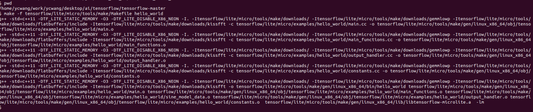
First, navigate to the main directory of the tensorflow source. Then run the following command:
make -f tensorflow/lite/micro/tools/make/Makefile test_hello_world_test
The results will be as shown in the following image

After analyzing the test program’s code, we also understand the entire program flow. The differences between the test program and the actual running program are minimal and can be directly analyzed against the source code. We will only display the results of the program’s execution.
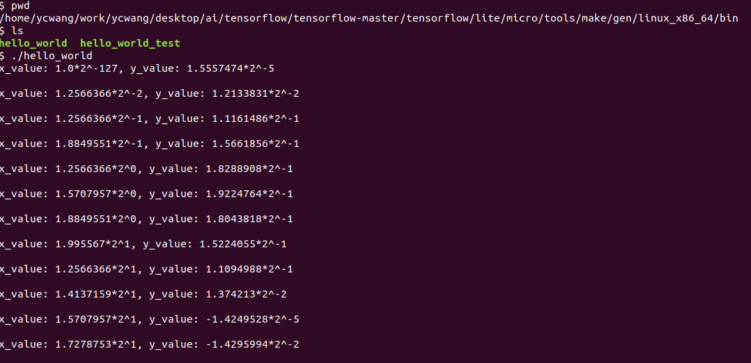
The program compiled normally. The compiled binary file for execution on the PC is located in the following directory under the tensorflow source root: tensorflow/lite/micro/tools/make/gen/.
On a Linux machine, the screenshot of the program running normally is as follows:
This lecture ends here; in the next lecture, we will analyze how to deploy existing projects onto hardware.
Hello World — The Place Where Dreams Begin (Part 2)
This article introduces how to load model code onto Arduino hardware and execute it. Meanwhile, TensorFlow Lite regularly adds support for new devices, so if the device you want to use is not listed here, you can visit this website for the latest information and check updated deployment instructions.
-
Websitehttps://github.com/tensorflow/tensorflow/blob/master/tensorflow/lite/micro/examples/hello_world/README.md
Each device has its unique output capabilities, ranging from a row of LEDs to a single LED or a full LCD display. Therefore, this example includes a custom implementation of HandleOutput() for each device.
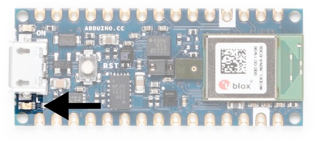
Various Arduino boards have different functionalities. Not all development boards can run TensorFlow Lite for Microcontrollers. We recommend the Arduino Nano 33 BLE Sense development board. The LED class of this board is shown in the following image:
Since we only have one LED to work with, we need to think creatively. One option is to change the brightness of the LED based on the latest predicted sine value. Given that the value ranges from -1 to 1, we can represent 0 with a completely off LED, -1 and 1 with a fully lit LED, and any intermediate value with a partially dimmed LED. The LED will repeatedly turn on and off as the program runs inference in a loop.
We can use the constant kInferencesPerCycle to change the number of inferences performed throughout the sine wave cycle. Since one inference takes some time, adjusting kInferencesPerCycle defined in constants.cc will adjust the speed at which the LED dims. The Arduino-specific version of this file is located in hello_world/arduino/constants.cc. The file’s name is the same as hello_world/constants.cc, so this file will be used in place of the original implementation when building applications for Arduino.
To dim the built-in LED, we can use a technique called Pulse Width Modulation (PWM). If we rapidly turn the output pin on and off, the output voltage of that pin becomes a factor of the time spent in the off and on states. If the pin spends 50% of the time in each state, its output voltage will be 50% of its maximum value; if it spends 75% in the on state and 25% in the off state, its voltage will be 75% of the maximum.
PWM is only available on certain pins of some Arduino devices, but it is easy to use: we just need to call a function to set the desired pin’s output level.
The code to implement Arduino output handling is in hello_world/arduino/output_handler.cc, replacing the original file hello_world/output_handler.cc.
Let’s browse through the source code:
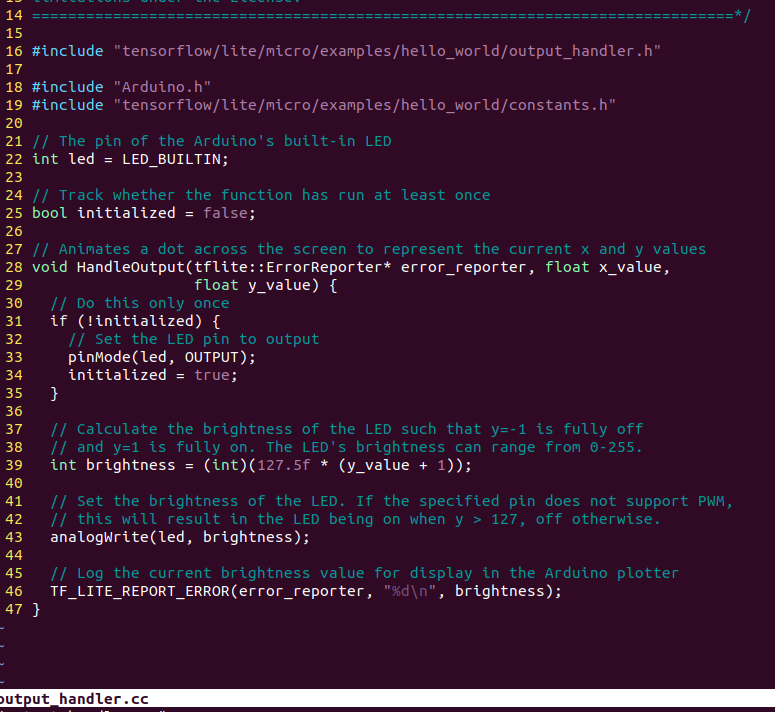
Let’s analyze several key parts of the source code:
First, we include some header files. Our output_handler.h specifies the files used for this. Arduino.h provides the interface for the Arduino platform; we use it to control the development board. Since we need access to kInferencesPerCycle, we also reference constants.h.
Next, we define a function and indicate what it should do on its first run:
// Adjust the LED brightness to represent the current y value
void HandleOutput(tflite::ErrorReporter * error_reporter, float x_value, float y_value) {
// Track whether the function has run at least once
static bool is_initialized = false;
// Only do this once
if (!is_initialized) {
// Set the LED pin as output
pinMode(LED_BUILTIN, OUTPUT);
is_initialized = true;
}
In C++, variables declared as static within a function will retain their value across multiple runs of that function. Here, we use the is_initialized variable to track whether the code block within the if(!is_initialized) has run before.
The initialization block calls Arduino’s pinMode() function, which indicates whether a given pin on the microcontroller should be in input or output mode; this must be done before using IO. This function uses LED_BUILTIN and OUTPUT provided by the Arduino platform. LED_BUILTIN indicates the pin connected to the built-in LED on the development board, while OUTPUT indicates the output mode.
After configuring the built-in LED’s pin as output mode, we set is_initialized to true so that this block of code will not run again.
Next, we calculate the desired LED brightness:
// Calculate the LED brightness to make y = -1 completely off
// and y = 1 completely on. The LED brightness ranges from 0-255.
int brightness = (int)(127.5f * (y_value + 1));
Arduino allows us to set the PWM output level to a number between 0 and 255, where 0 means completely off and 255 means completely on. Our y_value is between -1 and 1. The previous code maps y_value to the range of 0 to 255, so when y = -1, the LED is completely off; when y = 0, the LED is half lit; and when y = 1, the LED is fully lit.
The next step is to actually set the brightness of the LED:
// Set the LED brightness. If the specified pin does not support PWM,
// this will cause the LED to turn on when y > 127, otherwise it will turn off.
analogWrite(LED_BUILTIN, brightness);
The Arduino platform’s analogWrite() function takes a pin number (we provide LED_BUILTIN) and a value between 0 and 255. When we call this function, the LED will light up at that level.
Finally, we use the ErrorReporter instance to log the brightness value:
// Log the current brightness value to display in the Arduino plotter
error_reporter->Report("%d \n", brightness);
On the Arduino platform, the ErrorReporter is set up to log data via the serial port. The serial port is a very common way for microcontrollers to communicate with a host computer and is often used for debugging. It is a communication protocol where data is communicated one bit at a time by turning the output pin on and off. We can use it to send and receive anything from raw binary data to text and numbers.
The Arduino IDE includes tools for capturing and displaying data transmitted over the serial port. One such tool, the “Serial Plotter,” can graph the values it receives through the serial. By streaming our brightness values from our code, we will be able to see their graph. Next, we complete the entire execution process.
After running the Arduino development environment, open the Hello_world example.
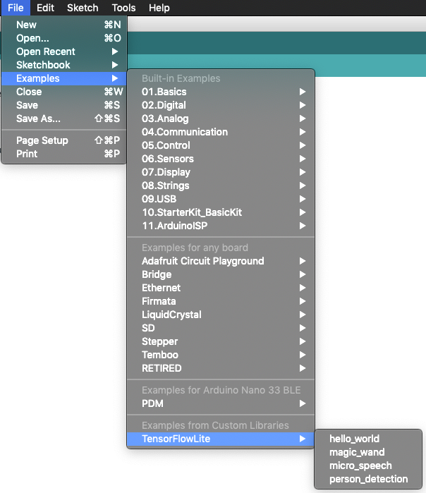
Then select the development board
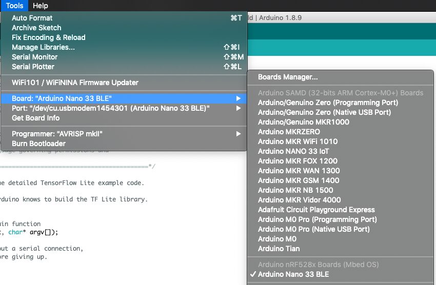
And perform the necessary library updates.
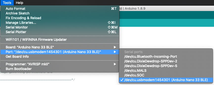
Select the serial port
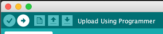
Run the program
View serial port data
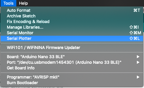
Display data graphs or raw data.