1. Development Environment
-
Espressif Integrated Development Environment <SDK> (Recommended)
-
Supports ESP8266 NONOS and FreeRTOS environment development (New version ESP8266 RTOS SDK V3.0 and above)
-
Supports ESP32 FreeRTOS environment development
-
Ready to use, no additional configuration required
-
Can directly compile the SDK development package released by Espressif
-
Graphical interface development
-
ESP8266 environment setup: http://wiki.ai-thinker.com/ai_ide_install
-
ESP8266 Documentation Center: http://wiki.ai-thinker.com/esp8266/docs
-
Arduino IDE Development Method (Recommended)
-
Advantages: Integrated programming and burning, very convenient to use. High execution efficiency, saves resources, has many library functions, and the development language is simple, allowing quick start.
-
Disadvantages: When writing longer code in Arduino IDE, it is not very convenient, and if you need to view low-level functions or methods, it can be very cumbersome. Therefore, we use VScode for development, because it has the best code suggestions.
-
AT Command Development (Not Recommended)
-
Advantages: Simple development, plenty of resources. Just need to know the AT command set and its communication method.
-
Disadvantages: Wastes resources, requires MCU to communicate, cannot complete a specific function independently.
-
Resources:
https://blog.csdn.net/lalala098/article/details/81240806
-
NodeMCU Lua Development (Not Recommended)
-
Advantages: Saves resources, simple development, less code.
-
Disadvantages: Lua interpreter execution efficiency is low, and it eventually switched to Arduino IDE development because it always missed a piece of data when reading sensor data. The initial preparation is more troublesome. Need to prepare the corresponding firmware, burn it in, and then use Lua language and tools to debug.
2. Setting Up Arduino Development Environment
2.1
Add ESP8266 Library
First, download the latest version of the Arduino IDE software from the Arduino Chinese Forum or the Arduino official website and install it.
After installation, go to Preferences, find the Additional Board Manager URLs, and add the following information: http://arduino.esp8266.com/stable/package_esp8266com_index.json
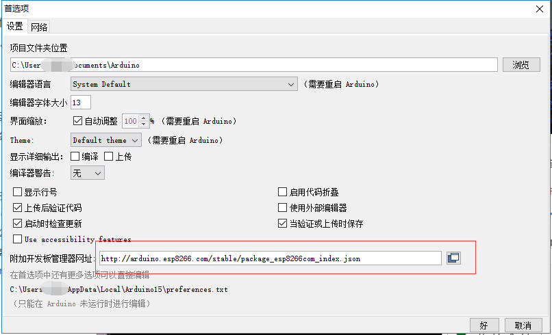
Configuration for overseas users
The above method is suitable for overseas users. Domestic users can directly download the package I provided below for installation.
https://www.jianguoyun.com/p/Dc1zwEcQ5TaCBjYmrMD
After downloading, just double-click to install.
After installation, you will find that many libraries have been added in the Project – Load Library, as shown in the figure below:
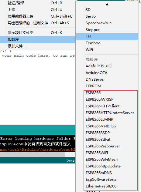
ESP8266 Libraries
You can also find many ESP8266 hardware added in Tools – Board (xxx), as shown in the figure below:
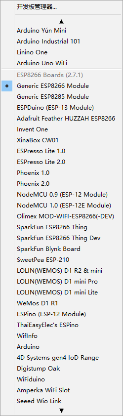
ESP8266 Hardware
Once this step is done, we can start burning the program. 😊
2.2
Burning Program Test
In this example, let’s become lighting engineers and light up our first LED.
We prepare the development board and find the pin that can light up the LED by referring to the schematic.
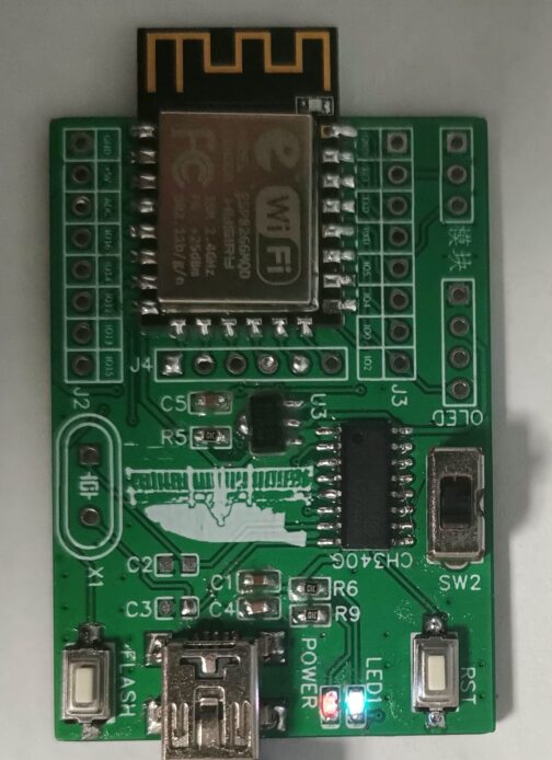
I have prepared a self-designed development board, similar to NodeMCU.
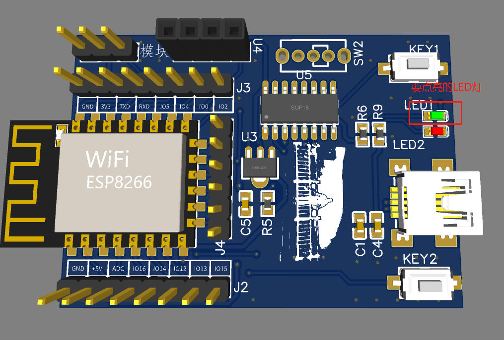
AD Model
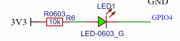
LED Schematic
From the diagram, we can see that when GPIO4 is low, LED1 will be lit. Knowing the logic for lighting, let’s make the LED blink. (Other boards are similar)
Source Code:
void setup() { // Set the "gpio4" pin to output state pinMode(4,OUTPUT);}void loop() { digitalWrite(4, HIGH); // Turn off LED delay(1000); // Wait for a second digitalWrite(4, LOW); // Turn on LED by pulling the pin low delay(1000); // Wait for a secondEffect:

The LED is actually blinking
3. Configure VScode Arduino Development Environment
3.1
Download Arduino Plugin
First, download the software from the VScode official website.
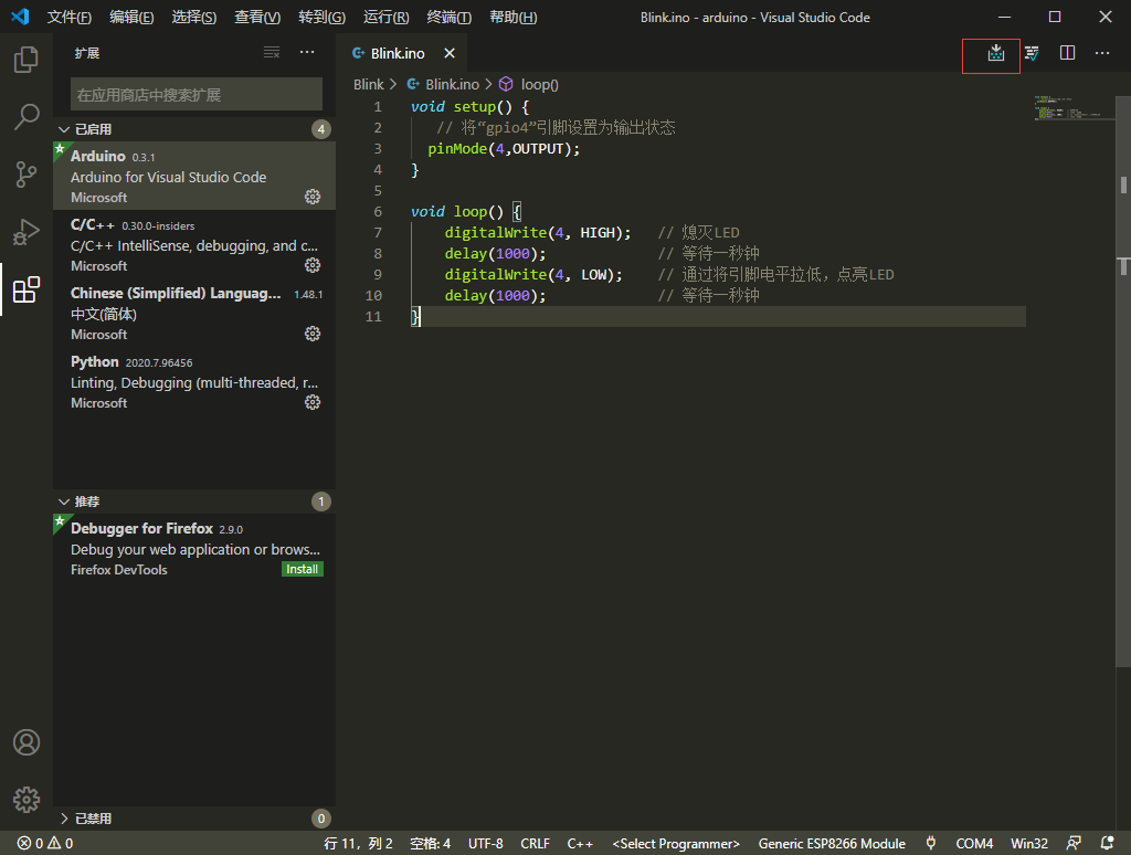
After installation, you can install the Arduino plugin as shown in the figure below.
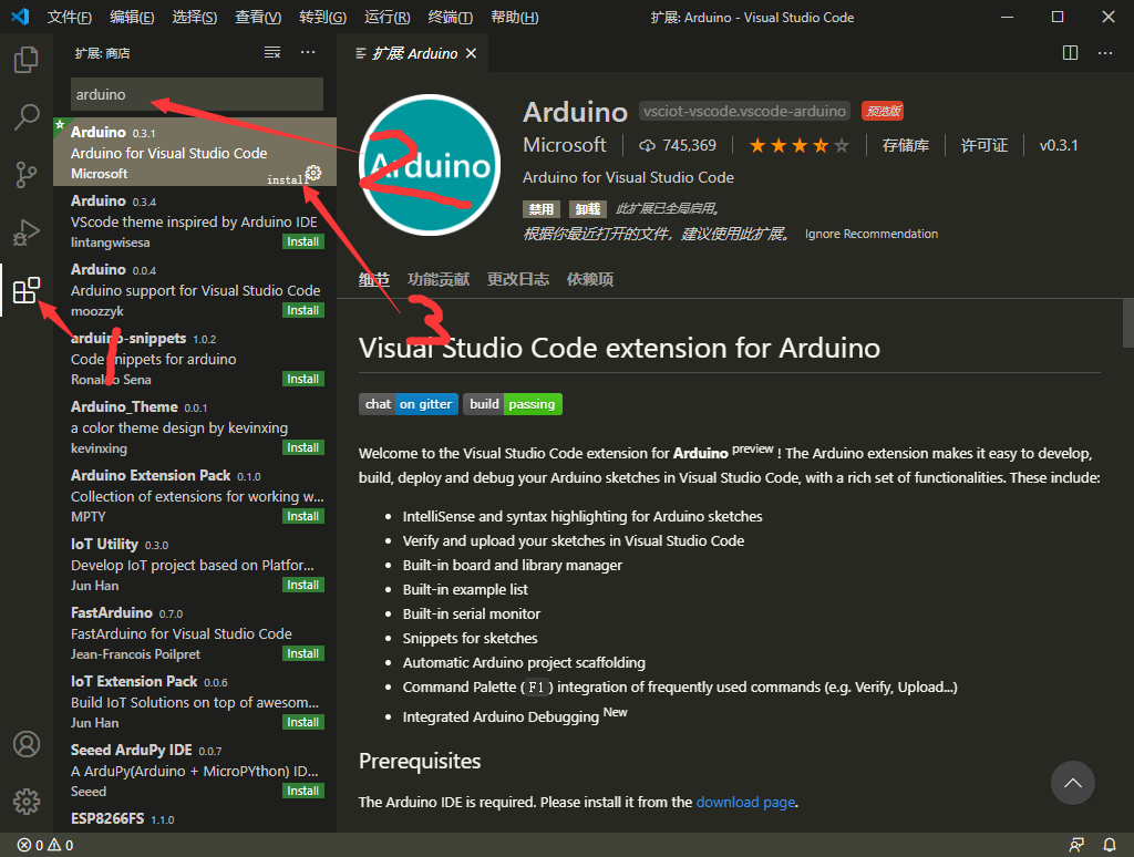
The third step does not show install because I have already installed it; those who haven’t installed it can directly click install.
3.2
Configure Arduino Plugin
-
First step: Set system parameters in VScode, press Ctrl+, to open and type arduino in the search box.
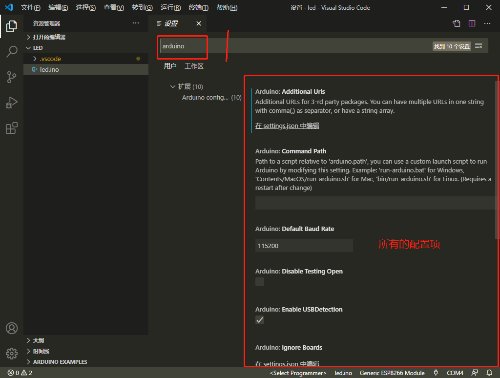
-
Second step: Find the Path in the configuration items, then enter the installation path of Arduino in the input box.
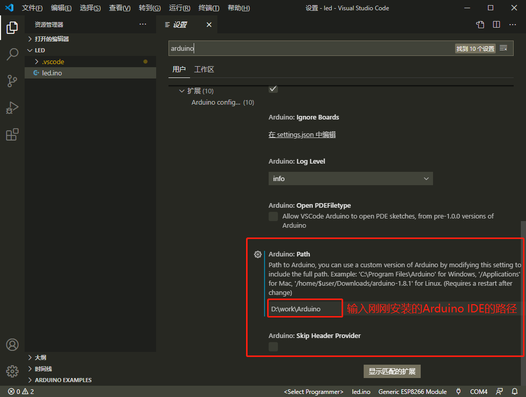
With this setting, VScode can run Arduino normally.
3.3
Create Arduino Program
Next, let’s demonstrate with the blink program.
First, open your Arduino directory with VScode, then create a folder named Blink and a file named Blink.ino.
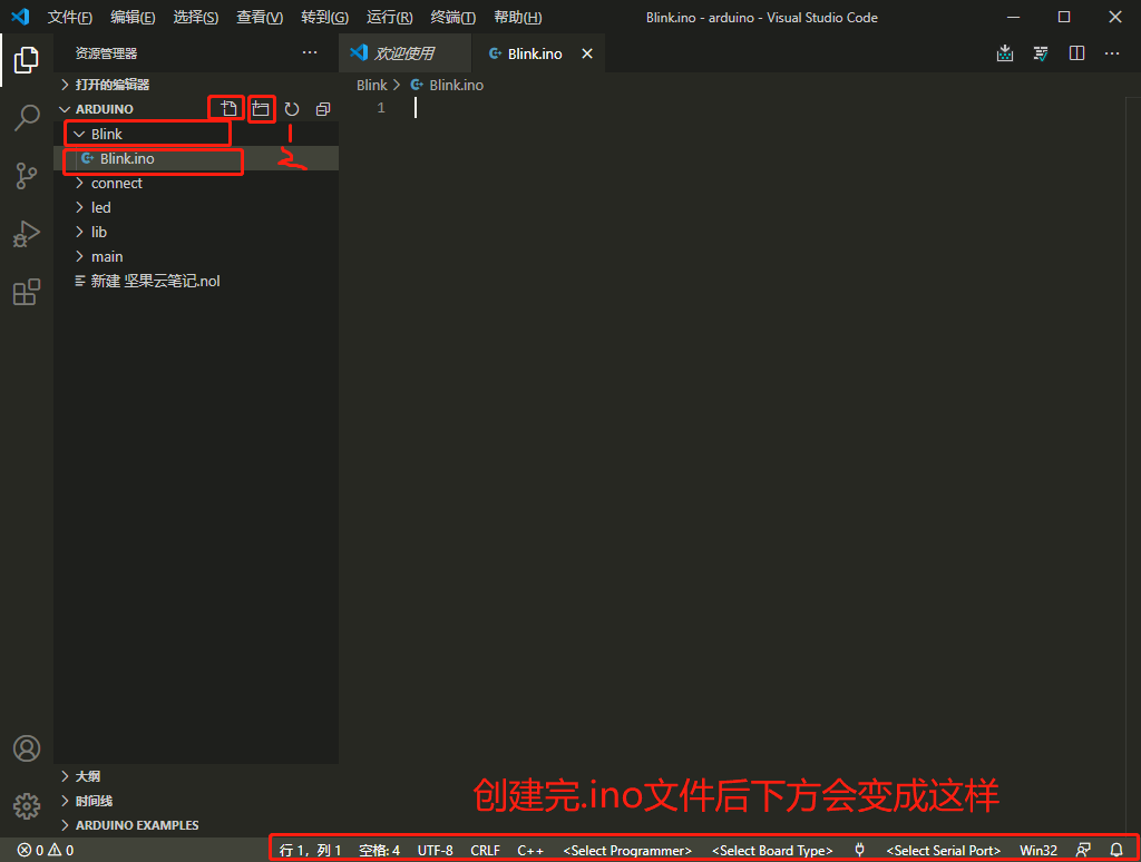
First, click on the <Select Board Type> in the status bar to select the board type. Here, since we are mainly learning about ESP8266, we select Generic ESP8266 Module.

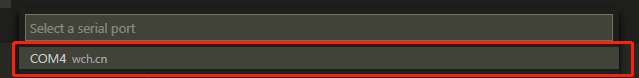
After selecting, connect your development board and click on <Select Serial Port> in the status bar to find your ESP8266 device port.
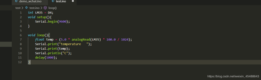
Now it’s time to write code.
Source Code:
void setup() { // Set the "gpio4" pin to output state pinMode(4,OUTPUT);}void loop() { digitalWrite(4, HIGH); // Turn off LED delay(1000); // Wait for a second digitalWrite(4, LOW); // Turn on LED by pulling the pin low delay(1000); // Wait for a secondQ1
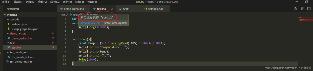
Why are there many red wavy lines?
When we are writing the program, we may find that there are no code suggestions in the editor, and there are many red wavy lines, thinking “Ah, the blogger is a fraud, clearly there are no code suggestions yet he took so long.”
Of course not! I will guide you through the pitfalls, and I will definitely guide you to fill them in together.
Solution:
In configuring the VS Code Arduino development environment, I encountered problems like this, such as error displays of undefined identifiers. There are many resources online about configuring the Arduino development environment in VS Code, so I won’t elaborate further. I just want to document the problems I encountered. The main issue is that the header file index is lost, and intellisense cannot automatically find the required header file paths. You need to force intellisense to use Tag Parser in user settings and recursively search for header files.
Add as follows:
First
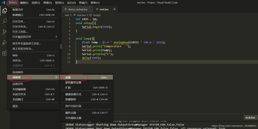
Next, enter Arduino in the input box to search.
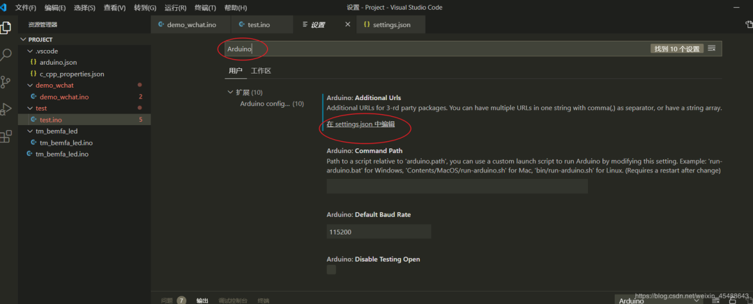
Open settings.json to configure related files:
Add the following 2 lines of code.
“C_Cpp.intelliSenseEngineFallback”: “Disabled”,
“C_Cpp.intelliSenseEngine”: “Tag Parser”,
Your configuration code is as follows:
Where “arduino.path”: “D:\work\Arduino”, is the path where Arduino is installed.
{ "window.zoomLevel": 0, "terminal.integrated.inheritEnv": false, "task.autoDetect": "off", "arduino.path": "D:\work\Arduino", "C_Cpp.updateChannel": "Insiders", "C_Cpp.intelliSenseEngineFallback": "Disabled", "C_Cpp.intelliSenseEngine": "Tag Parser", "arduino.additionalUrls": "", "workbench.colorTheme": "Monokai"}After saving, the undefined identifier error disappears.
Reference from:
https://blog.csdn.net/weixin_45488643/article/details/105966613
Alright, next is to download the program. Before downloading, it is important to know that the ESP8266 is in download mode only when GPIO15 is low during startup.
So here I need to press the flash button (pull GPIO15 low) and then press the RST button (this will put the ESP8266 into download mode).
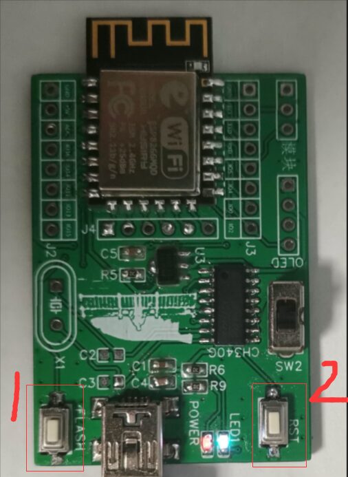
Once in download mode, we select the area highlighted in the figure below on our computer. It will start downloading automatically.
Q2
Output content appears garbled?
If there are no issues, move on~
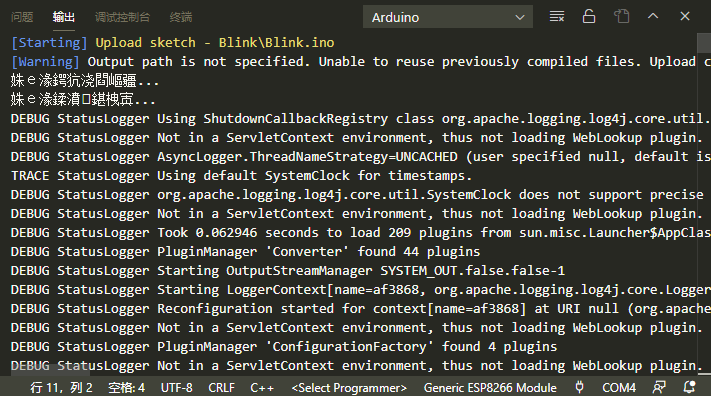
Solution:
1. Find the installation directory of the vscode Arduino extension, locate the util.js file, for example, on my computer (note that paths differ on different computers, usually found in the user folder; if you can’t find it, just search using the file manager):
C:\Users\Administrator\.vscode\extensions\vsciot-vscode.vscode-arduino-0.3.1\out\src\common\util.js2. Find the code around line 215 in the file as follows
if (os.platform() === "win32") { try { const chcp = childProcess.execSync("chcp.com"); codepage = chcp.toString().split(":").pop().trim(); } catch (error) { outputChannel_1.arduinoChannel.warning(`Defaulting to code page 850 because chcp.com failed.\ \rEnsure your path includes %SystemRoot%\\system32\r${error.message}`); codepage = "850"; }3. Comment out the above code
/* if (os.platform() === "win32") { try { const chcp = childProcess.execSync("chcp.com"); codepage = chcp.toString().split(":").pop().trim(); } catch (error) { outputChannel_1.arduinoChannel.warning(`Defaulting to code page 850 because chcp.com failed.\ \rEnsure your path includes %SystemRoot%\\system32\r${error.message}`); codepage = "850"; } } */4. Restart VScode
Final Effect:
Reference from:
https://blog.csdn.net/weixin_42225355/article/details/104906950
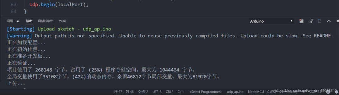
After solving the garbled issue, we see the content shown in the figure below after downloading, indicating that the download was successful. We just need to restart the ESP8266 (press the RST button) or power it again.

Effect:
The effect is consistent with the program downloaded using Arduino IDE.
4. Summary
This chapter is the second in this series. Some may ask, “Why does the AD model I provided look different from my soldered board?” In fact, I made a mistake in the design. I originally intended to use CH340G, but I didn’t notice the crystal oscillator wiring issue, which caused no response when connected to the computer. So I switched to CH340C, which has a built-in crystal oscillator, freeing up space for adding modules.
I will share the PCB schematic and program on my Gitee, and I would appreciate it if you could give my project a star. Thank you all.
Gitee link:
https://gitee.com/maochengkai/esp8266_from_entry_to_entry/tree/master
Please do not take my series of articles as the standard; there will always be oversights. If there are, please point them out, and feel free to leave a message!

Limited time offer for the course! Scan to view: