Software Development Tool: MPLAB X IDE v6.25MCC Configuration Tool: v5.5.2Chip Model: dsPIC33CK32MP502Principle Analysis: The DAC generates small segments of DC voltage. Since the duration of these small DC voltage segments is very short, they can be considered as a “point“, and many such segments can be stitched together to form a complete sine wave. As shown in the figure below: the red small segments represent the output voltage of the DAC, while the black waveform is the sine wave we need to simulate. Since the amplitude of the sine wave ranges from -1 to +1, but the dsPIC33CK32MP502 operates on a single supply voltage of +3.3V, we need to shift the sine wave upwards to ensure that the voltage amplitude of the generated sine wave signal is between 0-3.3V, making its minimum value 0.
 Raising the sine wave appropriately sets its amplitude to ensure that the overall amplitude is within (0, 3.3). The expression is as follows:
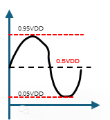
 However, upon reviewing the DAC user manual for the dsPIC33CK32MP502, we find that the output voltage range of the DAC is not 0-Vdd but rather 0.05Vdd~0.95Vdd. Therefore, the range of our sine function must also conform to this interval; otherwise, waveform distortion may occur (e.g., clipping of the peaks).
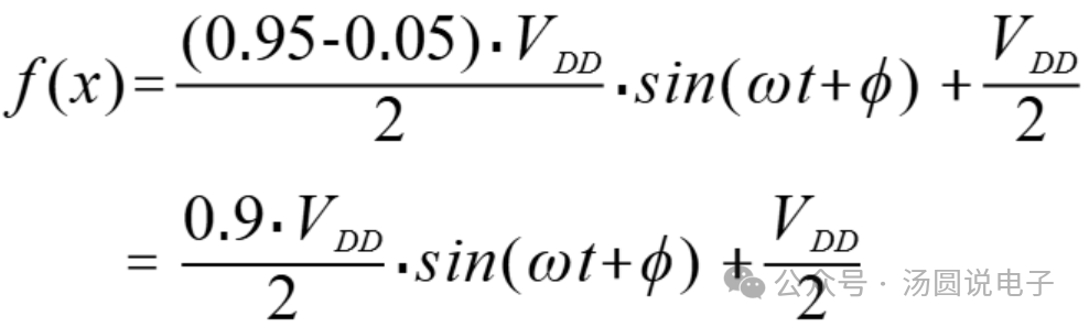
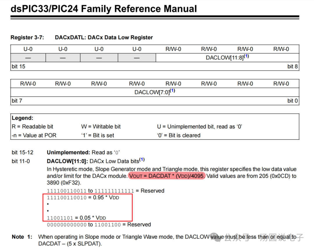 Redesign the sine function to ensure its value range meets the DAC requirements. Since the DAC’s value range is 0.05Vdd~0.95Vdd, the sine signal amplitude must be within this range, with its half-wave peak value being (0.95Vdd – 0.05Vdd)/2. Given that its minimum value is 0.05Vdd, the final center point value (the value when the sine angle is 0) is (0.95Vdd – 0.05Vdd)/2 + 0.05Vdd = 0.5Vdd, and the expression is as follows:
 We will divide one cycle (
 ) of the sine wave into 256 parts and convert the above formula into angular form, as shown below.
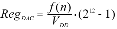
 The DAC register value calculation formula is as follows:
 The evolution of the DAC output voltage waveform is shown below:

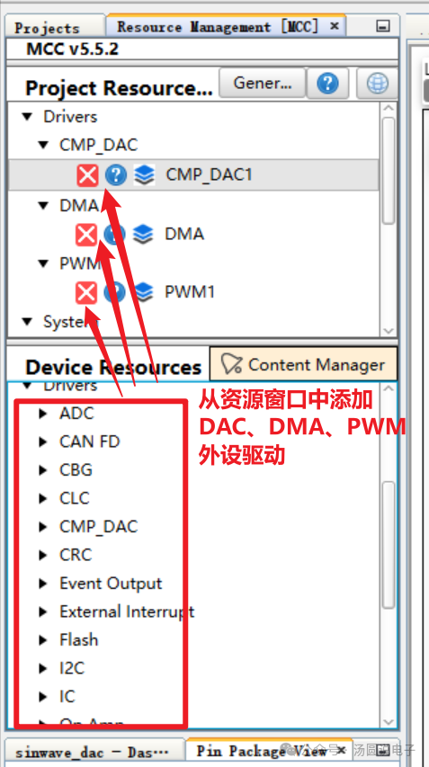
 MCC Peripheral Configuration Settings
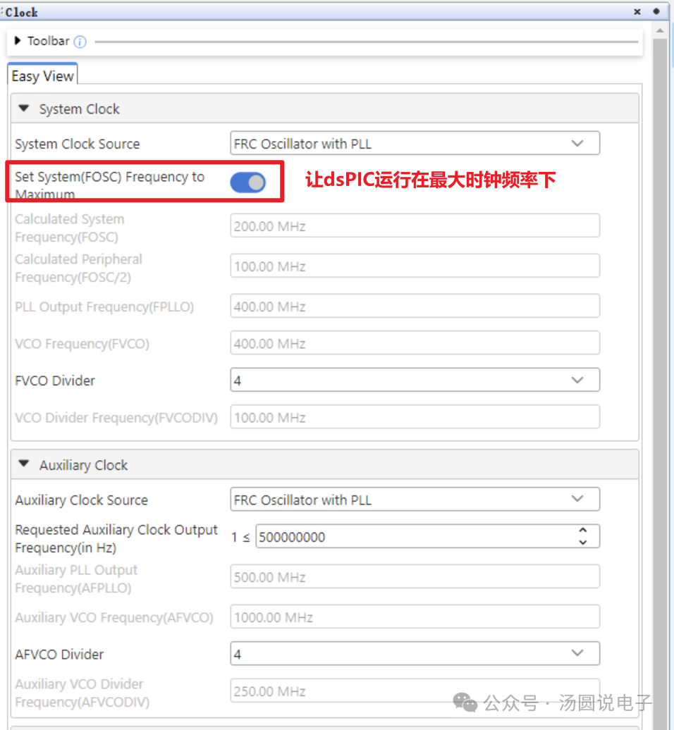
 Set System Clock
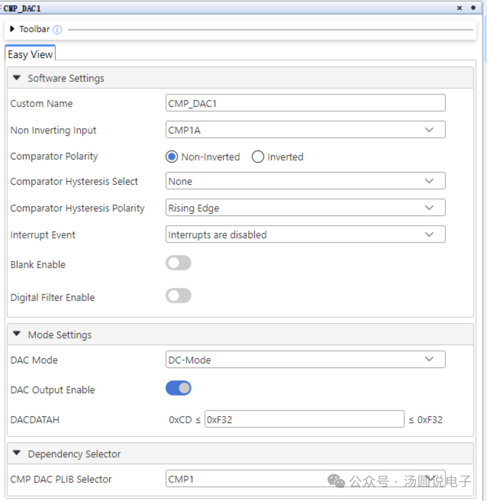
 DAC Settings
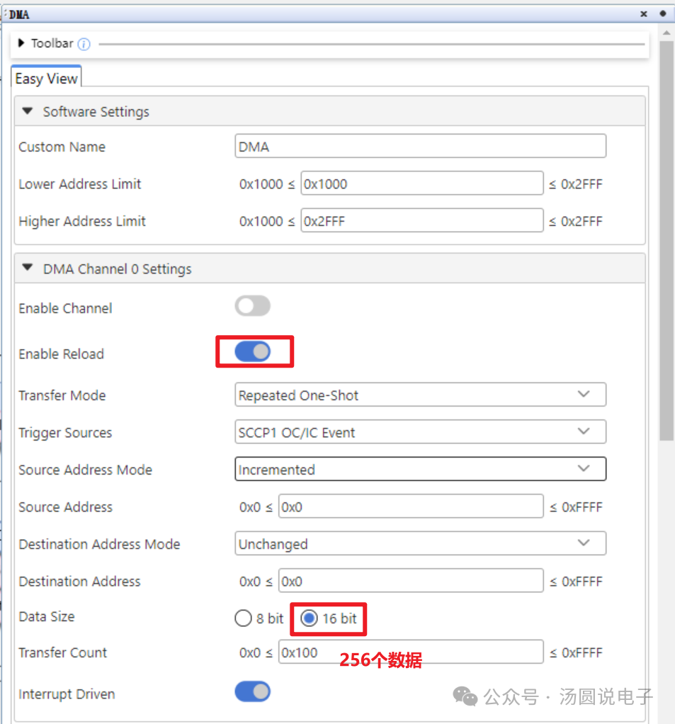
 DMA Settings: Since we have a fixed sine wave data array and the peripheral address is always the DAC data register address, we choose the Reload mode for the DMA. This way, the DMA will automatically reload the array address and DAC address. We use PWM to trigger the DMA to transfer data from the sine array to the DAC register, so we set the DMA trigger source to: SCCP1, which is the PWM frequency.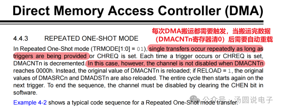
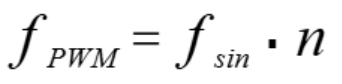
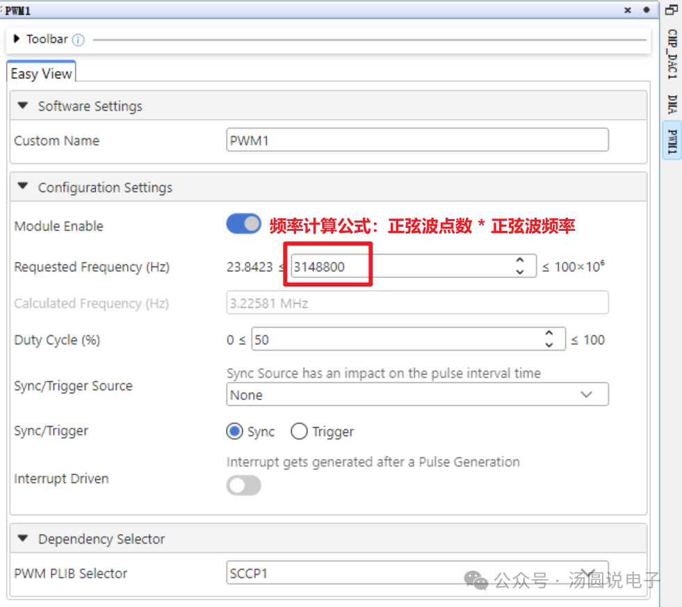
 PWM SettingsHow should the PWM frequency be set? Previously, we introduced that the sine wave is formed by stitching small segments of voltage output from the DAC. Here, we use 256 small segments to form a complete sine wave, so the number of elements in the sine wave data array is 256. Each time the PWM generates a waveform, it triggers the DMA to transfer, thus the PWM frequency equals 256 times the sine wave frequency:
 The required sine wave frequency is approximately 12kHz
 Set DAC Signal Output Pin
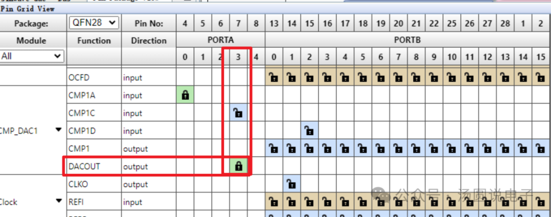 Add Code in main.c
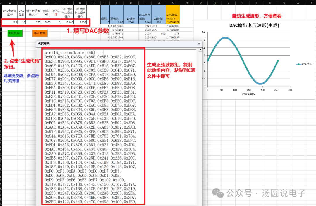
#include "mcc_generated_files/system/system.h"#include "mcc_generated_files/dma/dma.h"/* Main application*/int main(void){ uint16_t sineTable[256] = { 0x800, 0x82d, 0x85a, 0x887, 0x8b4, 0x8e1, 0x90e, 0x93a, 0x967, 0x993, 0x9bf, 0x9eb, 0xa16, 0xa41, 0xa6c, 0xa97, 0xac1, 0xaea, 0xb13, 0xb3c, 0xb64, 0xb8c, 0xbb3, 0xbd9, 0xbff, 0xc24, 0xc49, 0xc6d, 0xc90, 0xcb3, 0xcd5, 0xcf6, 0xd16, 0xd36, 0xd55, 0xd73, 0xd90, 0xdac, 0xdc7, 0xde2, 0xdfb, 0xe14, 0xe2c, 0xe43, 0xe58, 0xe6d, 0xe81, 0xe94, 0xea6, 0xeb7, 0xec6, 0xed5, 0xee3, 0xeef, 0xefb, 0xf05, 0xf0f, 0xf17, 0xf1e, 0xf24, 0xf29, 0xf2d, 0xf30, 0xf31, 0xf32, 0xf31, 0xf30, 0xf2d, 0xf29, 0xf24, 0xf1e, 0xf17, 0xf0f, 0xf05, 0xefb, 0xeef, 0xee3, 0xed5, 0xec6, 0xeb7, 0xea6, 0xe94, 0xe81, 0xe6d, 0xe58, 0xe43, 0xe2c, 0xe14, 0xdfb, 0xde2, 0xdc7, 0xdac, 0xd90, 0xd73, 0xd55, 0xd36, 0xd16, 0xcf6, 0xcd5, 0xcb3, 0xc90, 0xc6d, 0xc49, 0xc24, 0xbff, 0xbd9, 0xbb3, 0xb8c, 0xb64, 0xb3c, 0xb13, 0xaea, 0xac1, 0xa97, 0xa6c, 0xa41, 0xa16, 0x9eb, 0x9bf, 0x993, 0x967, 0x93a, 0x90e, 0x8e1, 0x8b4, 0x887, 0x85a, 0x82d, 0x800, 0x7d2, 0x7a5, 0x778, 0x74b, 0x71e, 0x6f1, 0x6c5, 0x698, 0x66c, 0x640, 0x614, 0x5e9, 0x5be, 0x593, 0x568, 0x53e, 0x515, 0x4ec, 0x4c3, 0x49b, 0x473, 0x44c, 0x426, 0x400, 0x3db, 0x3b6, 0x392, 0x36f, 0x34c, 0x32a, 0x309, 0x2e9, 0x2c9, 0x2aa, 0x28c, 0x26f, 0x253, 0x238, 0x21d, 0x204, 0x1eb, 0x1d3, 0x1bc, 0x1a7, 0x192, 0x17e, 0x16b, 0x159, 0x148, 0x139, 0x12a, 0x11c, 0x110, 0x104, 0xfa, 0xf0, 0xe8, 0xe1, 0xdb, 0xd6, 0xd2, 0xcf, 0xce, 0xcd, 0xce, 0xcf, 0xd2, 0xd6, 0xdb, 0xe1, 0xe8, 0xf0, 0xfa, 0x104, 0x110, 0x11c, 0x12a, 0x139, 0x148, 0x159, 0x16b, 0x17e, 0x192, 0x1a7, 0x1bc, 0x1d3, 0x1eb, 0x204, 0x21d, 0x238, 0x253, 0x26f, 0x28c, 0x2aa, 0x2c9, 0x2e9, 0x309, 0x32a, 0x34c, 0x36f, 0x392, 0x3b6, 0x3db, 0x400, 0x426, 0x44c, 0x473, 0x49b, 0x4c3, 0x4ec, 0x515, 0x53e, 0x568, 0x593, 0x5be, 0x5e9, 0x614, 0x640, 0x66c, 0x698, 0x6c5, 0x6f1, 0x71e, 0x74b, 0x778, 0x7a5, 0x7d2 }; SYSTEM_Initialize(); DMA.SourceAddressSet(DMA_CHANNEL_0, (uint16_t)&sineTable[0]); DMA.DestinationAddressSet(DMA_CHANNEL_0, (uint16_t)&DAC1DATH); DMA.ChannelEnable(DMA_CHANNEL_0); while(1) { } }Compile and run the effect, using an oscilloscope connected to the DAC output pin to observe its waveform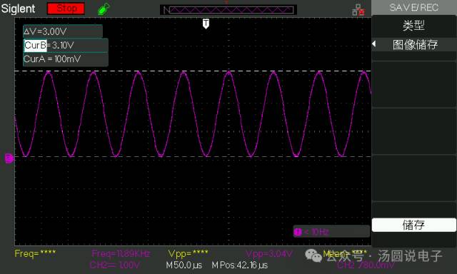 To facilitate the subsequent acquisition of DAC-generated sine wave array data, I created a small tool using Excel VBA for generating sine waves. Below is the usage of this tool. Please bear with me as the tool is somewhat rudimentary and has some minor issues.
 Import the sine wave array content to generate a sine wave graph and display the DAC register content in column M
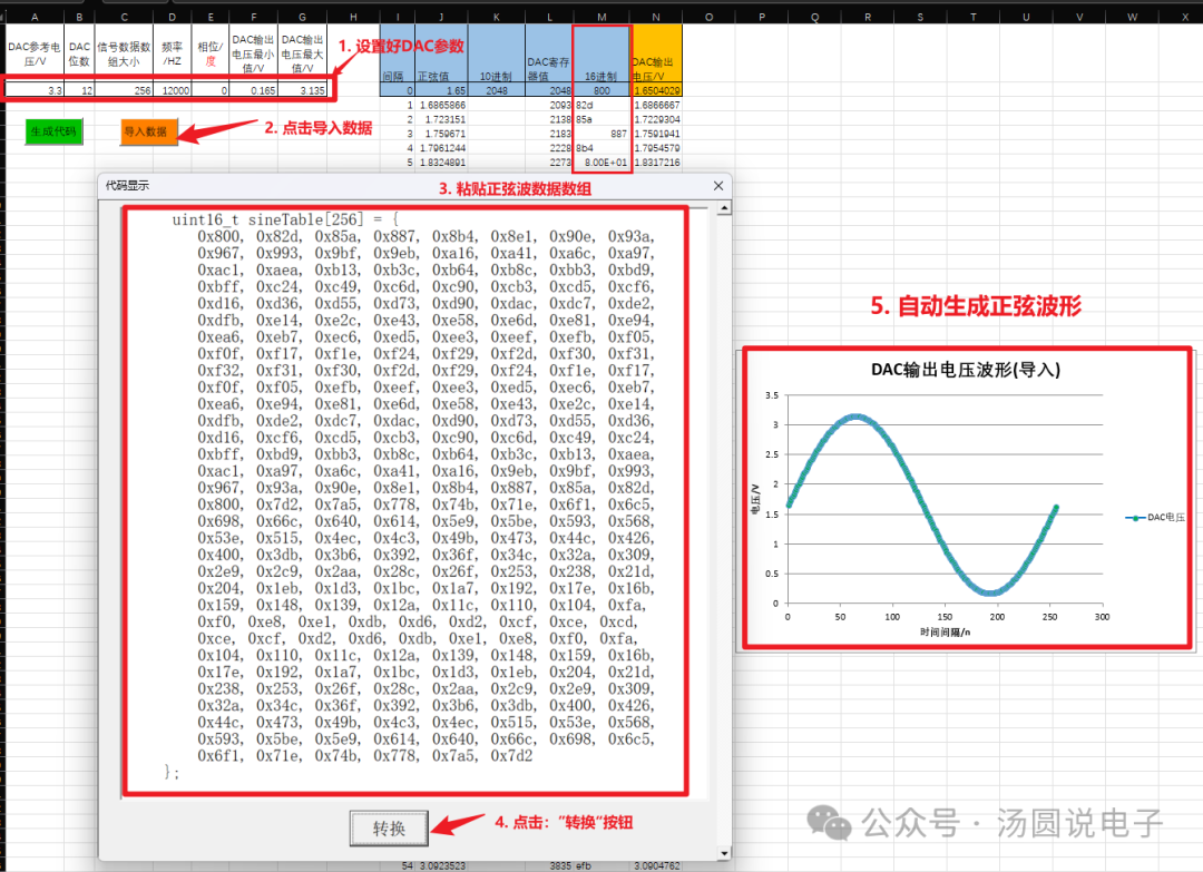 Note: Sometimes clicking the “Generate” button does not pop up the code display window; if this happens, please click a few more times.About Obtaining Chip Information
Chip information can be directly searched on the Microchip official website by entering the chip model, where all documentation can be found on the chip introduction page.
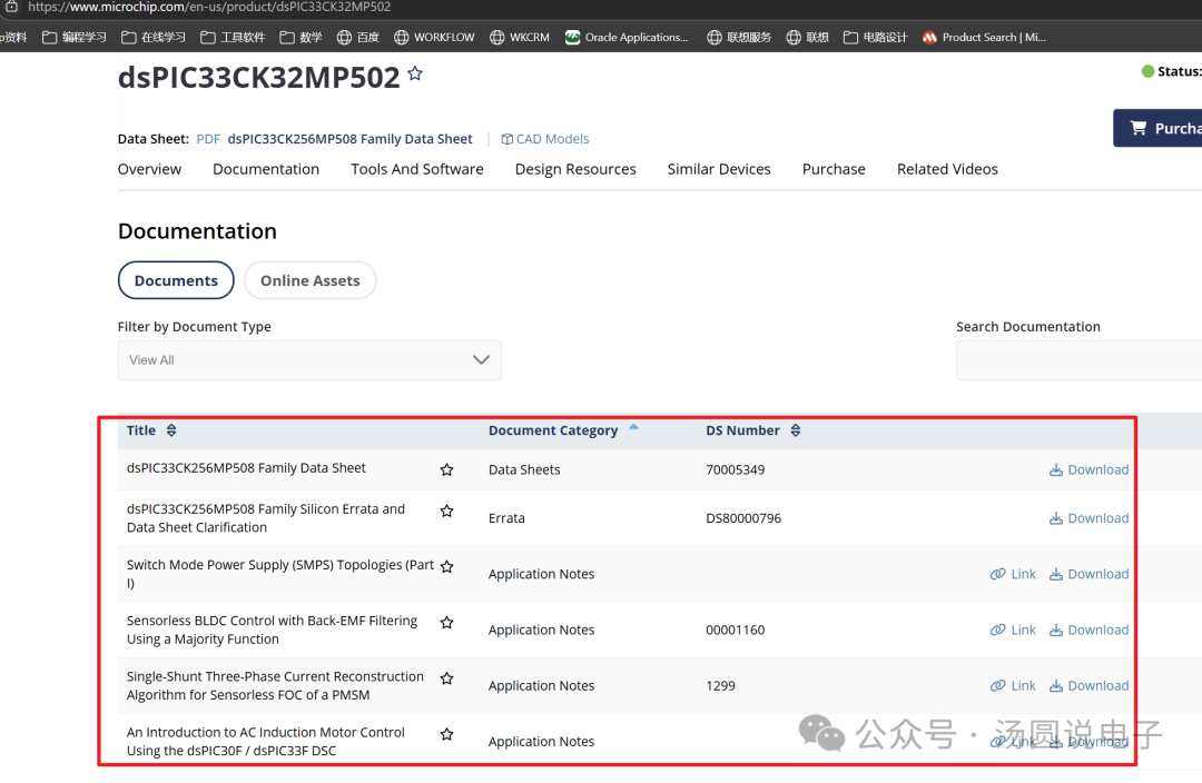 DAC User Manual:
https://ww1.microchip.com/downloads/aemDocuments/documents/MCU16/ProductDocuments/ReferenceManuals/dsPIC33-PIC24-FRM-High-Speed-Analog-Comparator-with-Slope-Compensation-DAC-DS70005280.pdf
Other Issues
Excel Query Errors and Handling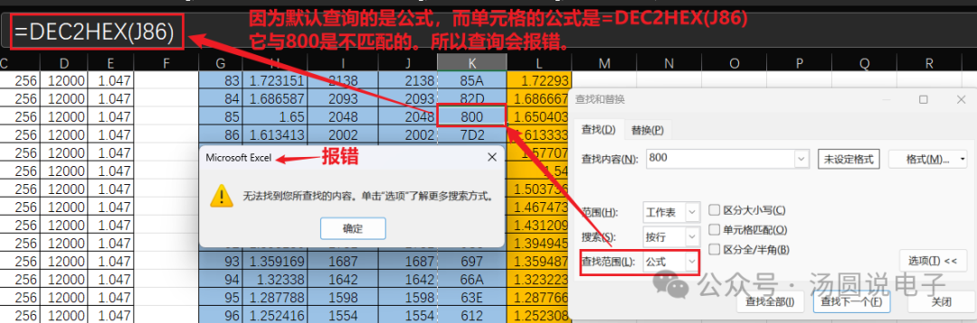 Querying by content will yield results
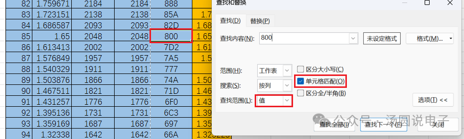 References:https://github.com/microchip-pic-avr-examples/dspic33ck-dac-dma-sinewaveFollow “Tangyuan Talks Electronics” and reply with the keyword: DAC-SIN, to obtain the extraction code
Files shared via cloud: DAC-Sinewave
Link: https://pan.baidu.com/s/1ZXFk2lQEaS0gN0eIr4-mjQ