Step 1: Create the physical chip.
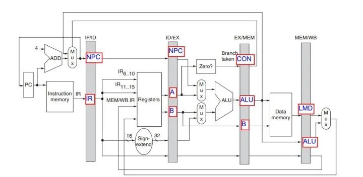
A microcontroller, generally understood as MCU (Microcontroller Unit), includes components such as timers, ALU (Arithmetic Logic Unit), memory, registers, buses, etc. A typical microcontroller also includes GPIO, serial ports (UART), DMA, coprocessors, AD/DA, etc.
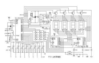
Understand the diagram below
Prerequisites: Computer Organization Principles, Microcomputer Principles.
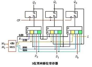
Prerequisites: Digital Logic Circuits, Integrated Circuit Design and EDA Technology, Verilog breaks down each module to the register level, such as shift registers, timers, decoders, memory, etc.
module minicpu(clk, reset, run, in, cs, pcout, irout, qtop, abus, dbus, out);
 input clk,reset,run; input [15:0] in; output [1:0] cs; output [15:0] irout, qtop, dbus, out; output [11:0] pcout, abus; wire [15:0] qnext, ramout, aluout; reg [11:0] abus; reg halt, jump, pcinc, push, pop, thru, qthru, dbus2qtop, dbus2ram, dbus2obuf, ir2dbus, qtop2dbus, alu2dbus, ram2dbus, in2dbus; reg pop2, ir2abus, qtop2abus, qnext2abus; reg [11:0] pcout, pcnext; reg [15:0] out;
 statef statef0(.clk(clk),.reset(reset),.run(run),.halt(halt),.cs(cs)); stackm stackm0(.clk(clk),.reset(reset),.load(dbus2qtop),.push(push),.pop(pop),.pop2(pop2),.thru(qthru),.d(dbus),.dthru(ramout),.qtop(qtop),.qnext(qnext)); alu alu0(.a(qtop),.b(qnext),.f(irout[4:0]),.s(aluout)); dpram #(16,10,1024) dpram0(.clk(clk),.load1(dbus2ram),.addr1(abus),.addr2(pcnext),.d1(dbus),.q1(ramout),.q2(irout));
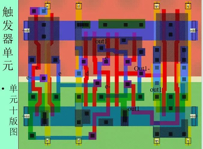
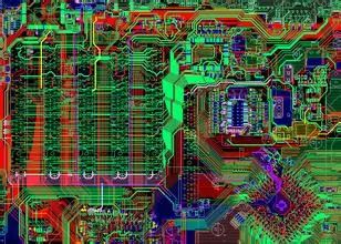
Physically it looks like this
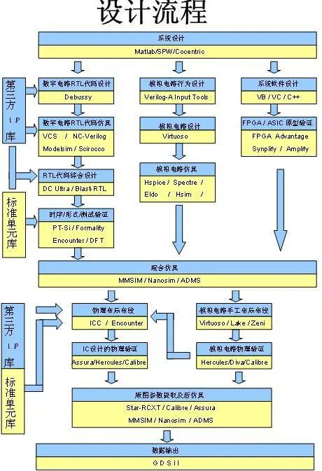
Then you will debug bugs and check the timing. Prerequisites: Timing using MODELSIM, synthesis using QUARTUS II, etc.
At this point, it has just begun. Continue to generate the circuit netlist, timing convergence, if not correct, return to the above process to continue debugging. Prerequisites: Synopsys
At this stage, layout files should be generated, and various design rule checks should be performed according to the physical device library provided by the manufacturer.
Prerequisites: Integrated Circuit Layout Design, Software: Cadence: Virtuoso Layout Editor
Send to the foundry, and you also need to understand components.
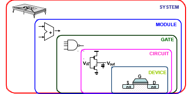
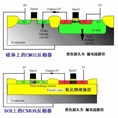
Prerequisites: Semiconductor Physics, Semiconductor Device Physics, Solid State Physics, Dielectric Physics, Quantum Mechanics, Thermodynamics and Mathematical Statistics.
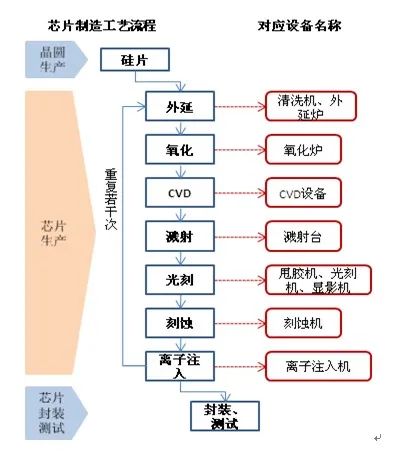
Based on the obtained diagrams, design the layout and process flow, roughly like this. Prerequisites: Integrated Circuit Manufacturing
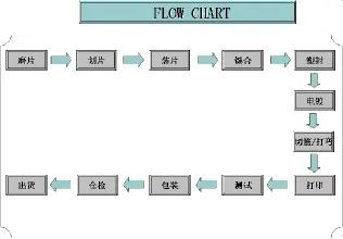
Then conduct electrical testing, electromagnetic testing, and finally packaging. Prerequisites: Integrated Circuit Packaging Technology
Finally, do not forget to burn incense, bathe, and change clothes when the chip is produced, bow three times facing south, and pray that there will be no major problems.
Step 2: Design the system driver.
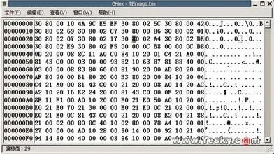
Finally, we have obtained the physical chip, and we start writing the assembler and compiler. Essentially, the machine code written into ROM looks like this.
Assembler (turns assembly language into machine code)
#!/usr/bin/perl -W//*****************//print "*** LABEL LIST ***\n";foreach $l (sort(keys(%label))){    printf "% -8s%03X\n",$l,$label{$l};}
$addr=0;print "\n*** MACHINE PROGRAM ***\n";foreach (@source){    $line = $_;    s/\w+://;    if(/PUSHI\s+(-?\d+)/){       printf "%03X:%04X\t$line",$addr++, $MCODE{PUSHI}+($1&0xfff);    } elsif(/(PUSH|POP|JMP|JZ|JNZ)\s+(\w+)/){       printf "%03X:%04X\t$line",$addr++, $MCODE{$1}+$label{$2};    }elsif(/(-?\d+)/){       printf "%03X:%04X\t$line",$addr++, $1&0xffff;    } elsif(/([A-Z]+)/){       printf "%03X:%04X\t$line",$addr++, $MCODE{$1};    } else {       print "\t\t$line";    }}
Compiler BISON and FLEX (converts high-level languages into assembly language)
Prerequisites: Compiler Principles
%{#include <stdio.h>%}%union {char *s; int n;}%token <s> NAME NUMBER%destructor { free($$); } NAME NUMBER%token <n> IF WHILE DO%type <n> if0%token GOTO ELSE INT IN OUT HALT......%%int yyerror(char *s){ printf("%s\n",s); }int main(){ yyparse(); }%{ #include <string.h> #include "y.tab.h" int n=0;%}......while {yylval.n=++n;return(WHILE);}[0-9]+ {yylval.s=strdup(yytext);return(NUMBER);}[a-zA-Z][a-zA-Z0-9]* {yylval.s=strdup(yytext);return(NAME);}. {return(yytext[0]);}%%int yywrap(){ return(1);}
Finally, you need a small piece of boot code to run the program, which can be solidified into ROM.
Prerequisites: Assembly Language
%{#include <stdio.h>%}%union {char *s; int n;}%token <s> NAME NUMBER%destructor { free($$); } NAME NUMBER%token <n> IF WHILE DO%type <n> if0%token GOTO ELSE INT IN OUT HALT......%%int yyerror(char *s){ printf("%s\n",s); }int main(){ yyparse(); }%{#include <string.h>#include "y.tab.h"int n=0;%}......while {yylval.n=++n;return(WHILE);}[0-9]+ {yylval.s=strdup(yytext);return(NUMBER);}[a-zA-Z][a-zA-Z0-9]* {yylval.s=strdup(yytext);return(NAME);}. {return(yytext[0]);}%%int yywrap(){ return(1);}
Then start writing the operating system. Prerequisites: ucos (Embedded Operating System)
System macro definitions, system function configurations, system header files, initialization files, scheduling files, task management files, system time management files, semaphore files, mailbox files, message queue files, memory management files, system service files, MAIN files.
Write tasks in the operating system. Prerequisites: C Language, Data Structures, Introduction to Algorithms.
start: JK startnopsdal 32sdah 0datploop: tinginltinginhjend cxcutenopjmp loopincexcute: call 32nopjmp startnop
With the painstaking board, you also need to configure the minimum system and peripheral devices. Prerequisites: PCB Design and Manufacturing, Soldering Skills, Analog Electronics, High-Frequency Electronic Circuits, Signals and Systems
If there is signal transmission communication protocol. Prerequisites: SPI, I2C, CAN, TCP/IP, Wi-Fi, etc.
uint SPI_RW(uint uchar){uint bit_ctr;for(bit_ctr=0;bit_ctr<8;bit_ctr++) // output 8-bit { MOSI = (uchar & 0x80); // output 'uchar', MSB to MOSI uchar = (uchar << 1); // shift next bit into MSB.. SCK = 1; // Set SCK high.. uchar |= MISO; // capture current MISO bit SCK = 0; // ..then set SCK low again }return(uchar); // return read uchar}
Prerequisites: Microwave Technology, Electromagnetic Fields and Waves, HFSS, Antenna Technology, etc.
The above answer is sourced from Zhihu, author: Peng Muwei
Link: https://www.zhihu.com/question/28580074/answer/93515413
After reading this classmate’s answer, netizens commented:
Chemistry, optics, semiconductor physics, etc., just the method of coating photoresist can keep you busy for a lifetime.
Is this a one-person job?
You can’t do this without a certain level of expertise, microelectronics major, haha, then go back to the past, and kill yourself.
Is the last picture a PCB layout or an IC?
… After reading, I no longer want to learn microcontrollers. Goodbye manually.
Okay, in just a few minutes, I experienced “From Beginner to Abandoning”.
︿( ̄︶ ̄)︿ Can’t be more detailed…
In fact, a friend from the 21ic forum once attempted to make a 51 microcontroller, next, enjoy the production process of netizen Yixibei:
The designed circuit schematic is as follows (PDF file and related detailed information can be found by clicking on the “Read Original” link):
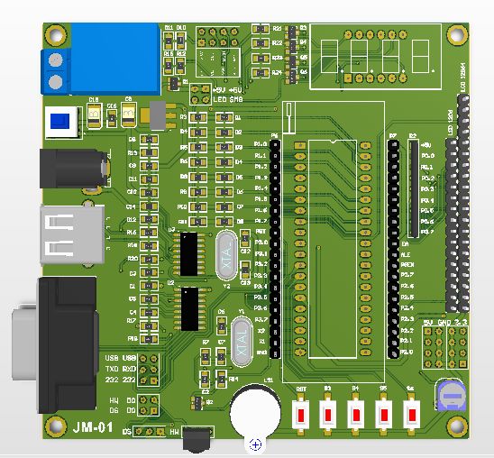
The PCB design is as follows, double-sided board, within 10*10 (printing is relatively cheap), the 3D effect diagram is as follows:
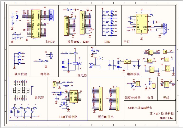
1. Onboard 8 LEDs can be used for light chasing experiments.
2. Onboard 4-digit seven-segment display can be used for static and dynamic display experiments.
3. Onboard CH340 download chip, can achieve one-click download via USB.
4. Onboard MAX232 serial port chip, now serial port downloading, serial port communication.
5. Onboard relay module, can control large current and voltage.
6. Onboard buzzer module, can serve as a prompt for related applications.
7. Onboard 1602 LCD interface, can display related character data in real-time.
8. Onboard 12864 LCD interface, can display Chinese character data in real-time.
9. Onboard four independent keys, can trigger some functions.
10. Onboard NRF24L01 wireless interface, achieving wireless transmission.
11. All IO ports are led out for easy debugging.
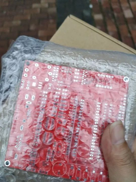
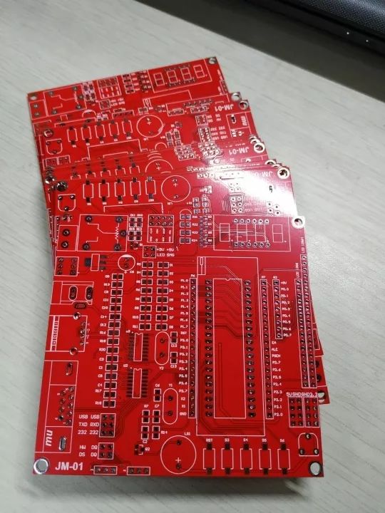
A few days later, I got the printed board, red is quite festive.
The soldering process is exhausting, so many chips make the process inevitably arduous.
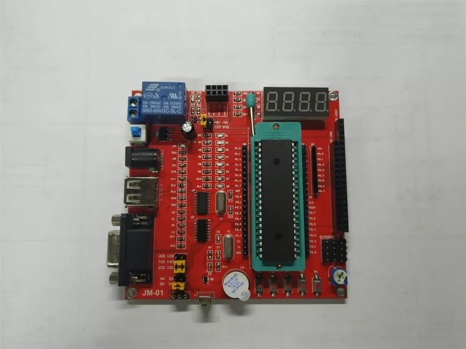
All done, a board is born, let’s try it quickly. The front view of the soldered board looks quite good.
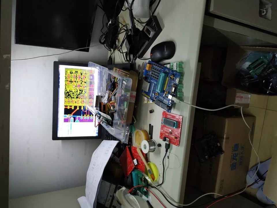
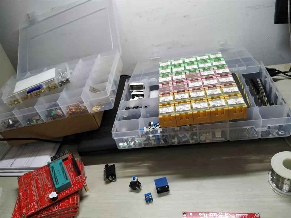
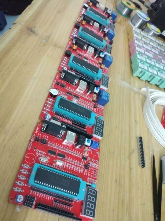
LED, seven-segment display, buzzer, relay all OK, USB CH340 download circuit is also OK, using Max232 DB9 serial port download is also OK, LCD interfaces 1602 12864 can also display normally, basically all functions are normal, this board production is quite successful. Taking advantage of this momentum, I soldered a few more boards, lined them up, and the sense of achievement is overwhelming.
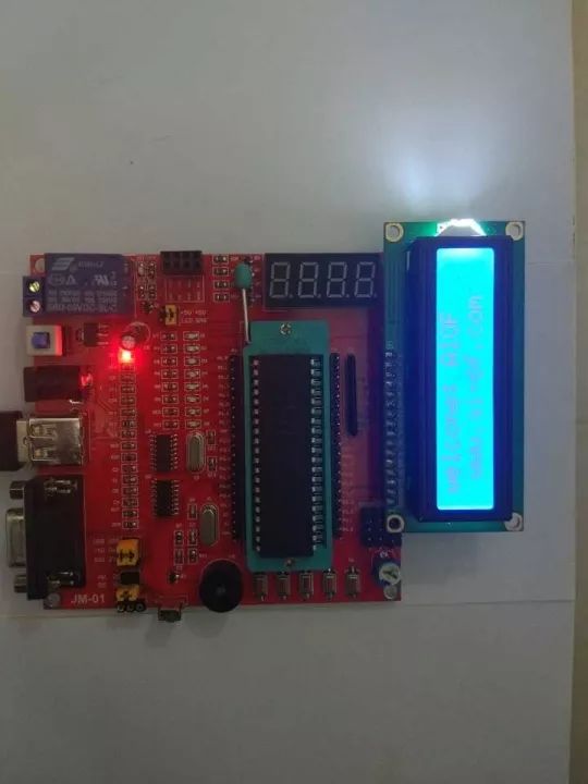
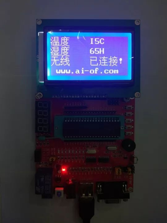
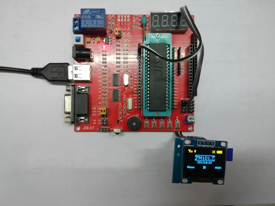
Here are some pictures of testing functions, including 1602, 12864, and OLED display.
Disclaimer:The article is transferred from “the internet”, and the copyright belongs to the author. If there is any infringement, please contact us for deletion!
Apply for Development Board for Free

🤞Long press the image to scan and apply🤞

