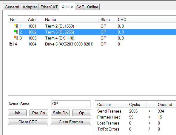
 The upper interface in the image displays the address, name, and state machine status of the slave device.The “CRC” column shows the cyclic redundancy check counter value of a single EtherCAT slave device at a certain moment. The cyclic redundancy check counters for ports A, B (if used), C (if used), and D (if used) are listed in order, separated by dots. When a port detects an error exposed by the cyclic redundancy check, the corresponding counter for that port will increment. Frames may be corrupted or damaged as they pass through the network. Errors detected by the cyclic redundancy check may be caused by cable faults, poor contact, loose plugs, or loose connectors.The lower interfaceThe “Actual State” text box displays the current state of the EtherCAT master. The buttons below can be used to manually switch the state of the EtherCAT master.The “Clear CRC” button is used to clear the cyclic redundancy check counters of the EtherCAT slave device.The “Clear Frames” button will reset all counters in the “Send Frames” table rows to zero.The “Cyclic” column displays information related to cyclic EtherCAT communication.The “Queued” column displays information related to acyclic EtherCAT communication.The “Lost Frames” row displays information related to lost transmission frames.The “Tx/Rx Errors” row shows data loss situations that occur during the sending and receiving process of the network card.