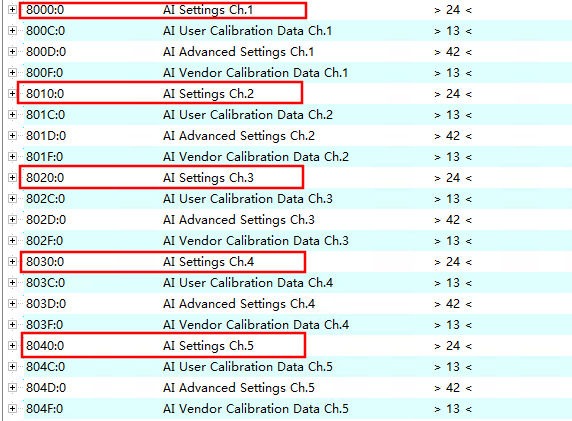
The device description file of the slave completely describes the parameters that can and cannot be changed in the device. Each parameter includes at least the following attributes:
-
Index Number — Used to uniquely identify all parameters. The index number consists of a “main index” and a “subindex” to group and arrange related parameters.
-
Main Index
-
Subindex, separated by a colon “:”
-
Official Name — Given in an easily understandable, self-explanatory text format.
-
Specification of Changeability — For example, read-only or read-write.
-
Value — Depending on the parameter type, the value can be text, a number, or an index pointing to another parameter.
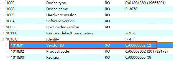
Example: For instance, the parameter “Vendor ID” in the figure below has an index number of 0x1018:01, with a value of “2” for the Beckhoff device ID. Since hexadecimal representation is commonly used in machine environments, the parameter appears to the user as:<span>0x1018:01 = 0x0002 (RO)</span> where RO (Read Only) indicates that this parameter is read-only, as the vendor ID should not be changed by the user.
CoE parameters can adopt various data types, including strings (text), integers, boolean values, or larger byte arrays, to describe various characteristics of the device. For example: manufacturer ID, serial number, process data configuration, device name, analog calibration values, or passwords, etc.
Application-oriented EtherCAT fieldbus users can focus on the following index ranges in the slave CoE:
-
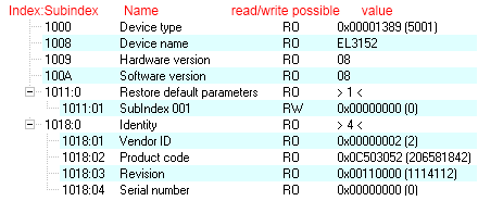
0x1000: Stores fixed identity information of the device, such as name, manufacturer, serial number, etc., as well as current and available process data configuration information.
-
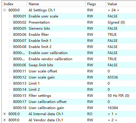
0x8000: Stores operational and functional parameters for all channels, such as filter settings or output frequency.
Other noteworthy ranges include:
-
0x4000: Some EtherCAT devices store channel parameters here (as an alternative to the 0x8000 range).
-
0x6000: Input PDO (viewed as “input” from the perspective of the EtherCAT master).
-
0x7000: Output PDO (viewed as “output” from the perspective of the EtherCAT master).
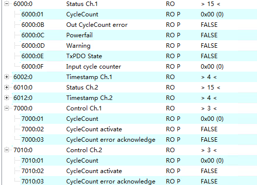
EtherCAT devices typically contain multiple channels with the same functionality, which is usually based on the arrangement of channels. For example, a 4-channel 0–10 V analog input terminal has 4 logical channels, each corresponding to a set of identical parameter data. To avoid listing each channel individually in the documentation, a placeholder “n” is often used to represent the specific channel number.
In the CoE system, 16 main indexes (with a maximum of 255 subindexes per main index) are generally sufficient to cover all channel parameters, so channel parameters are arranged in steps of 16 (decimal) / 0x10 (hexadecimal). For example, in the 0x8000 range:
-
Channel 0: 0x8000:00 … 0x800F:255
-
Channel 1: 0x8010:00 … 0x801F:255
-
Channel 2: 0x8020:00 … 0x802F:255
-
……
This representation is usually written as 0x80n0, where n is the channel number (0, 1, 2…).