
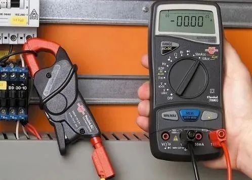
A multimeter, also known as a multimeter, three-in-one meter, or multifunction meter, is a versatile and multi-range measuring instrument. Generally, a multimeter can measure DC current, DC voltage, AC voltage, resistance, and audio levels. Some models can also measure AC current, capacitance, inductance, and certain parameters of semiconductors. It is a commonly used tool for electricians.

1. Check the range before measuring; do not measure without checking.
Each time you pick up the probes to prepare for measurement, be sure to double-check that the measurement category and range selection switch are set correctly. For safety, this habit must be developed.
2. Do not change the range while measuring; switch to the off position after measuring.
During measurement, do not arbitrarily turn the selection knob, especially when measuring high voltage (e.g., 220V) or high current (e.g., 0.5A), to avoid generating an arc that could damage the contact points of the switch. After measuring, the range selection switch should be turned to the “?” position.
3. The dial should be level; readings must be aligned.
When using a multimeter, it should be rotated to a level position, and the line of sight should be directly aligned with the needle when reading.
4. The range must be appropriate; the needle should deflect more than halfway.
When selecting a range, if the size of the measurement cannot be estimated in advance, try to select a larger range first, and then gradually switch to a smaller range based on the deflection angle until the needle deflects to about 2/3 of the full scale.
5. Measure resistance without power; discharge capacitors before measuring capacitance.
It is strictly forbidden to measure resistance in a live circuit. When checking large capacitors in electrical equipment, discharge the capacitor before measuring.
6. Zero the meter before measuring resistance; adjust to zero when changing ranges.
When measuring resistance, first turn the switch to the resistance setting, short the two probes, and adjust the “Ω” zero potentiometer so that the needle points to zero ohms before measuring. Each time the resistance setting is changed, the ohm zero point should be readjusted.
Measuring AC Voltage
Select AC on the range switch, ensuring the unit size matches the requirements;
Connect the probes to both ends of the circuit, with the positive and negative polarities correctly aligned;
When measuring high voltage, remember to change the socket; do not forget to switch off the power first;
Precautions for Using a Multimeter
When using an analog multimeter, connect one end of each measuring probe according to the requirement of red for positive (+) and black for negative (-) to the measuring terminals, then confirm whether the needle is at the “0” position. The needle should align with the left end line of the scale; if not, zero adjustment is necessary. Before measuring current and voltage, estimate the range of the current and voltage to be measured, starting with a larger range and then adjusting to an appropriate range to avoid burning out the multimeter due to excessive current.
During measurement, consider the impact of the multimeter’s internal resistance. For example, to measure voltage, connect the probes to the circuit being measured; at this point, current also flows through the multimeter’s internal resistance, which can affect the measurement value. When measuring the voltage at the same point using different ranges, the internal resistance of the multimeter varies, affecting the degree of impact.
When measuring transistor electronic circuits, it is better to select a DC range with an internal resistance of 20kΩ/V, which is usually marked on the multimeter’s scale. Additionally, transistor circuits often require measuring low voltages, such as 0.1V, so the selected multimeter should have a measurement range of 1V.
Disclaimer: This article is reprinted from the internet, and the copyright belongs to the original author. If there are any copyright issues, please contact us promptly for removal. Thank you!
Previous Recommendations:
Siemens PLC STL Programming Instruction Chinese-English Comparison Table, save for future reference!
Here comes the valuable content, a complete guide to three-phase electricity principles and connections!!!
Is short-circuiting the signal line useful? An experienced electrician reveals the truth!
Understanding the principles and maintenance of soft starters, shared by a repair expert with over ten years of experience!
9 classic Siemens PLC beginner programming cases, perfect for quick entry!
Click “Read the original text” to learn more industry knowledge!Your likes, follows, and shares are the greatest encouragement for the editor 💪